


Diode Overview: Application in Automotive Alternator Rectifiers
Introduction
At the beginning of automotive electronics technology, several electronic components have to be known, which are diodes, triodes, resistors, capacitors, and inductors. This article will take you into the wonderful world of electronics, and you will find the complex and boring electronic technology turned out to be very interesting.
Catalog:
ⅠWhat are the characteristics of a semiconductor?
ⅡIntrinsic Semiconductors, P-type semiconductors, and N-type Semiconductors
2.1 PN Junction and Diode
Ⅲ Working Principle of Diode
Ⅳ Types of Diode
Ⅴ The unidirectional conductivity of the diode
Ⅵ The Main Parameters of the Diode
Ⅶ What is the volt-ampere characteristic curve of the diode?
Ⅷ How to test the Quality of the Diode?
Ⅸ Diode Applications in Daily Life
ⅩApplication of Diodes in Automotive Alternator Rectifiers
ⅠWhat are the Characteristics of a Semiconductor?
In nature, according to the ability of materials to conduct electricity, we can divide them into conductors, insulators, and semiconductors. Common conductors such as copper and aluminum, and common insulators such as rubber, plastic, etc. What is a semiconductor? The conductivity of semiconductors is between that of conductors and insulators. Common semiconductor materials are silicon (Si) and germanium (Ge). At this point, remember two semiconductor materials: silicon and germanium. Because you will hear about silicon tubes and germanium tubes in the future. The meaning is obvious, indicating that this diode or triode is based on silicon or germanium.
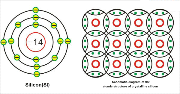
Figure2:Semiconductor silicon atomic structure diagram
There are several characteristics of semiconductors that need to be understood: thermal sensitivity, photosensitivity, and doping;
- Thermal sensitivity of semiconductors: The conductivity of semiconductors is greatly affected by temperature. When the temperature rises, the conductivity of semiconductors is greatly enhanced, which is called the thermal sensitivity of semiconductors. The thermal sensitivity of semiconductors can be used to make thermal components. The thermal components used in automobiles include temperature sensors, such as water temperature sensors and intake air temperature sensors.

Figure3:Schematic diagram of holes and free electrons in semiconductor silicon
- Photosensitivity of semiconductors: The conductivity of semiconductor conductors varies with light exposure. When the light is enhanced, the conductivity is improved, which is called semiconductor photosensitivity. Photosensitive elements can be made by using photosensitivity. Photosensitive elements in automobiles include light sensors used in automobile automatic air conditioning.
- Doping of semiconductors: When a small number of impurities are added to the conductors, the conductivity of the semiconductors increases.
Ⅱ Intrinsic Semiconductors, P-type semiconductors, and N-type Semiconductors
- Intrinsic Semiconductors: Pure semiconductors are called intrinsic semiconductors.
- P-type semiconductor: Doping a small amount of trivalent element boron (B) or gallium into the intrinsic semiconductor silicon or germanium forms a P-type semiconductor.
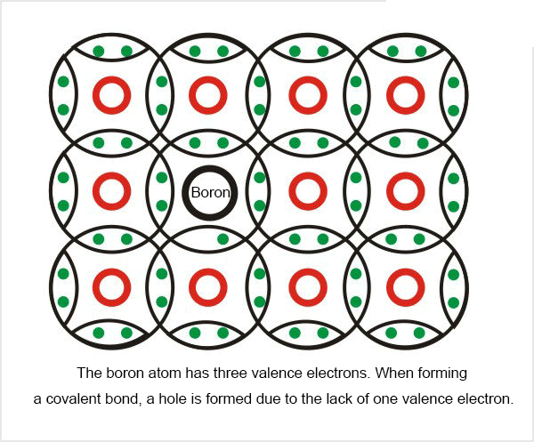
Figure4:N-Schematic diagram of a P-type semiconductor - holes are the majority carriers
- N-Type semiconductor: Doping a small amount of pentavalent element phosphorus (P) into the intrinsic semiconductor silicon or germanium forms an N-type semiconductor.
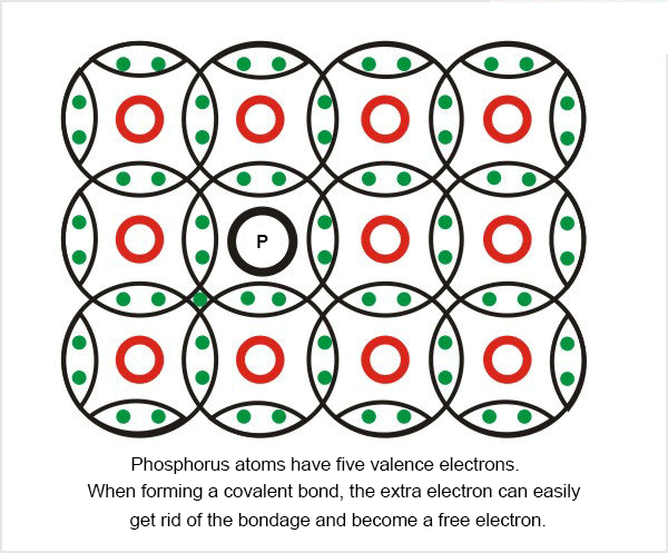
Figure5:Free electrons are the majority carriers in N-type semiconductors
2.1 PN Junction and Diode
A small amount of boron, a trivalent element, is doped into a part of the semiconductor silicon or germanium to make it P-type, and a small amount of phosphorus, a pentavalent element, is doped into another part of the area to make it an N-type semiconductor. A PN junction is formed at the junction of P-type and N-type semiconductors. A PN junction is a diode, the lead in the P region is called the anode, and the lead in the N region is called the cathode.
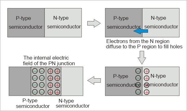
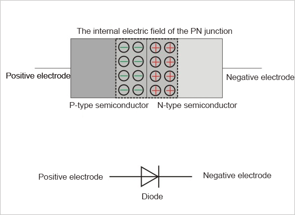
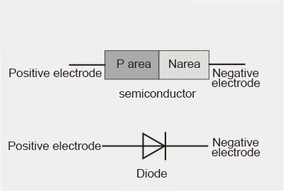
Figure 6-7-8:Diode structure diagram: the lead in the P area becomes the anode, and the lead in the N area becomes the cathode
Ⅲ Working Principle of Diode
A crystal diode is a p-n junction formed by a p-type semiconductor and an n-type semiconductor, and a space charge layer is formed on both sides of the interface, and a self-built electric field is built. When there is no external voltage, the diffusion current caused by the carrier concentration difference on both sides of the p-n junction is equal to the drift current caused by the self-built electric field, and it is in a state of electrical balance.
When the outside world has a forward voltage bias, the mutual suppression of the external electric field and the self-built electric field increases the diffusion current of the carriers and causes a forward current.
When there is a reverse voltage bias outside, the external electric field and the self-built electric field are further strengthened to form a reverse saturation current I0 that is independent of the reverse bias voltage value within a certain reverse voltage range.
When the applied reverse voltage reaches a certain level, the electric field strength in the space charge layer of the p-n junction reaches a critical value to generate a multiplication process of carriers, resulting in a large number of electron-hole pairs, resulting in a large reverse breakdown current. , known as the breakdown phenomenon of the diode.
Ⅳ Types of Diode
There are many diodes, which can be divided into germanium diodes (Ge tubes) and silicon diodes (Si tubes) according to the semiconductor materials used. According to their different uses, they can be divided into detection diodes, rectifier diodes, Zener diodes, switching diodes, etc. According to the die structure, it can be divided into point contact diodes, surface contact diodes, and planar diodes. Point-contact diodes use a very thin metal wire to press on the surface of a smooth semiconductor wafer, and pass a pulse current to make one end of the contact wire and the wafer firmly sintered together to form a "PN junction". Because it is a point contact, only a small current (no more than tens of milliamperes) is allowed to pass, and it is suitable for high-frequency and low-current circuits, such as radio detection.
The "PN junction" of the surface contact diode has a large area, allowing a large current (several amps to tens of amps) to pass through, and is mainly used in the "rectification" circuit that converts alternating current into direct current.
The planar diode is a special silicon diode. It can not only pass a large current but also has stable and reliable performance. It is mostly used in switches, pulses, and high-frequency circuits.
Ⅴ The Unidirectional Conductivity of the Diode
Diodes have front unidirectional conductivity,
- Forward conduction: When the PN junction is applied with a forward voltage, that is, when the P area is connected to the positive pole of the battery and the N area is connected to the negative pole of the battery, the PN junction is in the conduction state. As shown in the figure, the test lamp has current passing through it. Bright.
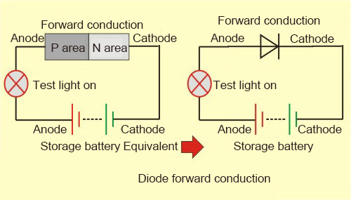
Figure 9:Diode forward conduction diagram
Note that there is a voltage drop when the diode is conducting forward, what does it mean? If the battery voltage is 12V, then the voltage on the test lamp must be less than 12V, about 11.6V, where is 0.4V? On a diode, this 0.4V is the voltage drop across the diode. The voltage drop of the diode depends on whether the diode uses a germanium tube or a silicon tube: the voltage drop of the germanium tube is about 0.2V, and the voltage drop of the silicon tube is about 0.5V. If the battery voltage is lower than the voltage drop over which the diode normally conducts, the diode will not conduct. You may not realize the importance of this principle in diodes, but it is very important when it comes to triodes.
- Reverse cut-off: When the reverse voltage is applied to the PN junction, that is, when the P area is connected to the negative pole of the battery and the N area is connected to the positive pole of the battery, the PN junction is in the cut-off state. As shown in the figure, the test lamp has no current flow and cannot be turned on.
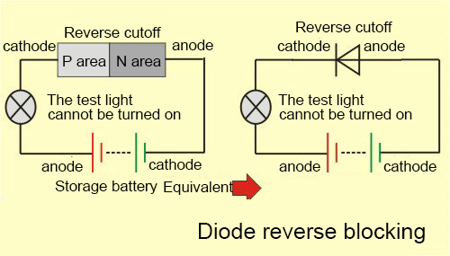
Figure 10:Diode reverse cut-off diagram
When the diode is connected to the reverse voltage, there is a problem with withstand voltage: if the reverse voltage applied to the diode is too high, the diode cannot bear it, and it will break down. At this time, the diode is not in the cut-off state, but in the conduction state. If we set a breakdown voltage, when the reverse breakdown voltage is reached, the diode will break down and conduct. What happens to the diode if the voltage is now less than the breakdown voltage? Ordinary diodes, it is still in the conduction state at this time, which means that the diode has lost its reverse cut-off function. A Zener diode will be mentioned later. We set a breakdown voltage. When the reverse breakdown voltage is reached, the diode will break down and conduct. If the voltage is now less than the breakdown voltage, the diode returns to the off state.
Ⅵ The Main Parameters of the Diode
The technical indicators used to indicate the performance and scope of application of the diode are called the parameters of the diode. Different types of diodes have different characteristic parameters. For beginners, the following main parameters must be understood:
1 Rated forward working current
It refers to the maximum forward current value allowed to pass through the diode when it works continuously for a long time. Because when the current passes through the tube, the tube core will heat up, and the temperature will rise. When the temperature exceeds the allowable limit (about 140 for the silicon tube and about 90 for the germanium tube), the tube core will be overheated and damaged. Therefore, the diode should not exceed the rated forward operating current value of the diode. For example, the commonly used germanium diode of type IN4001-4007 has a rated forward operating current of 1A.
2 The highest reverse working voltage
When the reverse voltage applied to both ends of the diode reaches a certain value, the tube will break down and lose its unidirectional conductivity. To ensure the safety of use, the maximum reverse working voltage value is stipulated. For example, the reverse withstand voltage of the IN4001 diode is 50V, and the reverse withstands voltage of IN4007 is 1000V.
3 Reverse current
The reverse current refers to the reverse current flowing through the diode under the specified temperature and the highest reverse voltage. The smaller the reverse current, the better the unidirectional conductivity of the tube. It is worth noting that the reverse current has a close relationship with temperature and the reverse current doubles for every 10% increase in temperature. For example, if the reverse current of a 2AP1 type germanium diode is 250uA at 25, and the temperature rises to 35, the reverse current will rise to 500uA, and so on. At 75, its reverse current has reached 8mA, not only lost The unidirectional conductivity will also cause the tube to overheat and be damaged. Another example is the 2CP10 type silicon diode, the reverse current is only 5uA at 25, and the reverse current is only 160uA when the temperature rises to 75. Therefore, silicon diodes have better stability at high temperatures than germanium diodes.
Ⅶ What is the Volt-ampere Characteristic Curve of the Diode?
After understanding the structure and working principle of the diode, there is a curve: the volt-ampere characteristic curve of the diode; I think everyone needs to understand it. The volt-ampere characteristic curve is the relational curve between the voltage applied to the diode (in volts) and the diode current (in amps).
On the volt-ampere characteristic curve of this diode, it can be divided into two parts: the forward characteristic and the reverse characteristic, and several important working parameters of the diode can be reflected from it: Interpretation of the volt-ampere characteristic curve of the diode
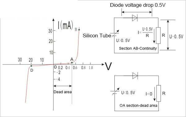
Figure 11:Bending Analysis of Diode's Forward Volt-ampere Characteristics
Forward characteristics of the diode: forward voltage is applied to both ends of the diode; when the voltage is lower than 0.5V (silicon tube), the flowing current is 0, and the voltage of 0.5V at this time is called the dead zone voltage; when the voltage is higher than the dead zone voltage At this time, the diode is turned on, and there is a voltage drop of about 0.5V on the diode at this time.
When the forward voltage is applied to the diode, two important parameters of the diode can be seen:
(1) Forward voltage drop: the smaller the better;
(2) Forward current: If the diode is used for rectification, it must be considered;
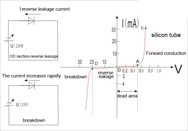
Figure 12:Bending Analysis of Reverse Volt-ampere Characteristic of Diode
The reverse characteristics of the diode: the reverse voltage is applied to both ends of the diode; when the voltage is lower than 20V (as shown in the figure), although the diode is cut off, there is still a small reverse leakage current; when the voltage is greater than 20V, the reverse The voltage breaks down the diode and the current increases rapidly.
When the reverse voltage is applied to the diode, we can see two important parameters of the diode:
(3) Reverse leakage current: the smaller the better;
(4) Reverse breakdown voltage: When the diode is used for rectification, it must be considered
Ⅷ How to Test the Quality of the Diode?
A multimeter can test the performance of the diode. Before the test, first turn the switch of the multimeter to the RX1K gear of the ohm gear (be careful not to use the RX1 gear, so as not to burn out the diode due to excessive current), and then short-circuit the red and black test leads to zero the ohm.
- Positive characteristic test
Put the black pen of the multimeter (the positive pole inside the meter) to the positive pole of the diode, and the red pen (the negative pole inside the meter) to the negative pole of the diode. If the needle does not swing to 0 but stops in the middle of the dial, the resistance at this time is the forward resistance of the diode. Generally, the smaller the forward resistance, the better. If the forward resistance is 0, it means that the die is short-circuited and damaged, and if the forward resistance is close to an infinite value, it means that the die is broken. Short-circuited and open-circuited pipes cannot be used.
- Reverse characteristic test
Touch the red test lead of the multimeter to the positive pole of the diode, and the black test lead to the negative pole of the diode. The tube is qualified if the pointer points at or near an infinite value.
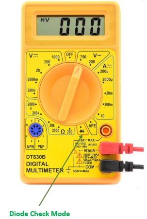
Figure13: Digital Multimeter
Ⅸ Diode Applications in Daily Life
- Rectifier diode
Using the unidirectional conductivity of the diode, the alternating current with alternating directions can be transformed into a pulsating direct current with a single direction.
- Switching element
Under the action of forward voltage, the resistance of the diode is very small, and it is in the on state, which is equivalent to an on-the switch; under the action of reverse voltage, the resistance is considerable, and it is in the off state, just like an off switch. Using the switching characteristics of diodes, various logic circuits can be formed.
- Limiting components
After the diode is forward-conducting, its forward voltage drop remains basically unchanged (0.7V for the silicon tube and 0.3V for the germanium tube). Utilizing this characteristic can be used as a limiting element in the circuit to limit the signal amplitude within a certain range.
- Follow-up diode
Acts as a relay in the inductance of switching power supplies and inductive loads such as relays.
- Detection diode
Plays the role of detection on the radio.
- Varactor diode
It is used in the tuner of the TV.
ⅩApplication of Diodes in Automotive Alternator Rectifiers
The main application of diodes is rectification, which can convert alternating current to direct current. For single-phase alternating current, four diodes are needed to form a rectification circuit. This rectification circuit is called a bridge rectification circuit.
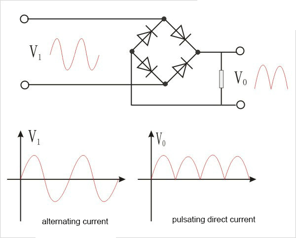
Figure 14:Diode bridge rectifier circuit
But for single-phase alternating current, the diode bridge rectifier circuit just reverses the negative half cycle of the alternating current, so the direct current at this time is a dynamic direct current.
Currently, the car generator uses a three-phase alternating current, and the internal diode rectifier converts the alternating current into direct current, requiring at least six diodes.
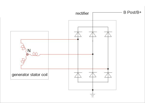
Figure 15:Application of Diodes in Automotive Alternator Rectifiers
The phase difference of the three-phase alternating current is 120 degrees. After diode rectification, the highest voltage interval of each phase is taken, so the voltage after rectification is connected to pure direct current.
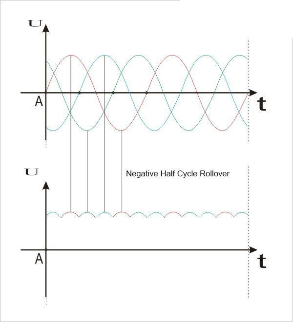
Figure 16:After the three-phase alternating current is rectified by diodes, the waveform is stable

 A Comprehensive Guide to Grasping FPGA Structure6/20/2024 842
FPGA (Field-Programmable Gate Array) is an integrated circuit, a type of programmable chip, that allows engineers to program custom digital logic. It can change its hardware logic based on the program, with the primary purpose of enabling engineers to redesign and reconfigure their chips faster and cheaper, whenever they want. However, nothing in the world is ideal, and FPGA chips also have limitations!
Read More > The EU to Impose Tariffs on Electric Vehicle Imports from China in Early July6/17/2024 409
The EU to Impose Tariffs on Electric Vehicle Imports from China in Early July
Read More > What is XC7A100T-2FG484I?6/6/2024 604
XC7A100T-1CSG324C is an FPGA-based digital signal processing board, which consists of Xilinx's Virtex-7 series chips and FPGA interface chips.
Read More > Analog cycle inventory hits bottom, AI drives flash memory demand to continue6/4/2024 634
Analog cycle inventory hits bottom, AI drives flash memory demand to continue
Read More >
Hot News
- Electronic Component Symbols: Resistor, Capacitor, Transformers and Connectors
- Diode Overview: Application in Automotive Alternator Rectifiers
- Ultra-low power consumption of STM32U575/585 microcontrollers(MCU)
- Voltage-Controlled Oscillator: Principle, Type Selection, and Application
- What is Xilinx 7 Series FPGA Clock Structure- -Part two
- Zedboard zynq-7000: Zynq 7000 datasheet, Features, Architecture and Core Components
SUPPORT
ABOUT BITFOIC
QUICK LINKS
Connect with us
Tel: 86-755-23606554
E-mail: [email protected]
Address: Room A29, 24 / F, Hoi Tak Wai, Prince Edward industrial building, 706 Prince Edward Road East, San Po Kong, Kowloon,Hongkong
Mon-Fri: 09.30 AM - 18.30 PM


