


Electronic Component Symbols: Resistor, Capacitor, Transformers and Connectors
Introduction
Electronic components are components of electronic components and small machines and instruments. They are often composed of several parts and can be used in similar products. They often refer to certain parts of industries such as electrical appliances, radios, and instruments. They are capacitors, transistors, and the general term for electronic devices such as hairsprings and springs. Common ones include diodes, etc. This post will introduce some kinds of basic electronic component symbols.
All Electronic Circuit Diagram Symbols || Basic Electronic Component Name And Symbol
Catalog
ⅠWhat is the Function of the Electronic Component in a Circuit?
Ⅱ Resistor and Potentiometer Symbols
2.1 Several Special Resistor Symbols
Ⅲ Capacitor Symbol
Ⅳ Symbols for Inductors and Transformers
Ⅴ Symbols for Microphones, Pickups, and Recording Heads
Ⅵ Symbol for Speakers, Headphones
Ⅶ Symbols for Wiring Elements
7.1. Switch Symbols
7.2 Connector Symbol
Ⅷ Relay Symbol
Ⅸ Battery and Fuse Symbols
Ⅹ Symbols of Diode and Triode
Ⅺ Symbols for Thyristors, Unijunction Transistors, and Field Effect Transistors
ⅠWhat is the Function of the Electronic Component in a Circuit?
An electronic component is a basic element in an electronic circuit, usually individually packaged, and has two or more leads or metal contacts. Electronic components must be connected to each other to form an electronic circuit with specific functions, such as amplifiers, radio receivers, oscillators, etc. One of the common ways to connect electronic components is to solder them to a printed circuit board. Electronic components may be individual packages (resistors, capacitors, inductors, transistors, diodes, etc.), or groups of varying complexity, such as integrated circuits (op amps, resistors, logic gates, etc.).
Circuit diagrams illustrate the working principle of analog electronic circuits. It uses various graphic symbols to represent real objects such as resistors, capacitors, switches, and transistors and uses lines to connect components and unit circuits according to their working principles.
This article mainly introduces the complete set of symbols for electronic components.
Ⅱ Resistor and Potentiometer Symbols
The symbols are shown in Figure ① in detail, where:
(a) represents a generally fixed resistance resistor;
(b) means a semi-adjustable or trimming resistor;
(c) indicates a potentiometer;
(d) represents a potentiometer with a switch.
The symbol of the resistor is "R", and the potentiometer is "RP", PR indicates that it has an adjustment function.
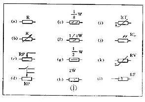
Figure2:Resistor and Potentiometer Symbols
In some circuits, there are certain requirements for the power of the resistor, which can be represented by the symbols shown in (e), (f), (g), and (h) in Figure 1.
2.1 Several special resistor symbols
- The first type is the thermistor symbol, and the resistance value of the thermistor changes with the external temperature. NTC represents a negative temperature coefficient, while PTC represents a positive temperature coefficient. Its symbol is in figure (i), and the temperature is represented by θ or t°. Its text symbol is " RT ".
- The second type is a photoresistor symbol, see Figure 1 (j), with two oblique arrows representing light. Its symbol is " RL ".
- The third is the symbol of the piezoresistor. The resistance of a varistor varies with the voltage applied across the resistor. See Figure 1(k) for the symbols, and the character U represents the voltage. Its symbol is " RV ".These three resistors are actually semiconductor devices, but we still treat them as resistors by convention.
- The fourth special resistor symbol is to represent the newly appeared fuse resistor, which has the function of both resistor and fuse.
When the temperature exceeds 500° C, the resistance layer will peel off and fuse quickly, cutting off the circuit, which can protect the circuit. Its resistance value is extremely small, and it is currently used in color TVs. Its graphic symbol is shown in Figure 1 (1), and its text symbol is "RF".
Ⅲ Capacitor symbol
See Figure ② for details, where:
(a) means a capacitor with fixed capacity;
(b) Indicates polarized capacitors, such as various electrolytic capacitors;
(c) represents a variable capacitor with adjustable capacity;
(d) denotes a trimmer capacitor;
(e) represents a double-connected variable capacitor. The literal symbol for a capacitor is C.
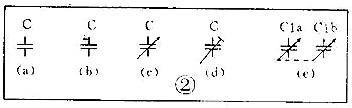 Figure3:Capacitor symbol
Ⅳ Symbols for Inductors and Transformers
The graphic symbols of the inductance coil in the circuit diagram are shown in Figure ③.
(a) is the general symbol of the inductance coil;
(b) is a coil with a magnetic or iron core;
(c) is a coil with a core gap;
(d) is an adjustable inductance with an adjustable magnetic core;
(e) is an inductance coil with multiple taps;
The text symbol of the inductor coil is "L".
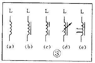
Figure4: Symbols for Inductors and Transformers
The graphical symbol of the transformer is shown in Figure ④:
(a): an air-core transformer;
(b): a Zinc or Iron core transformer;
(c): an iron core transformer with a shielding layer between windings;
(d): a transformer with a center-tapped secondary;
(e): a variable coupling transformer;
(f): an autotransformer;
(g): a transformer with an adjustable magnetic core;
The small dots in (h) are markings for the polarity of the transformer.
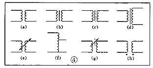
Figure5: Symbols for Inductors and Transformers
Ⅴ Symbols for Microphones, Pickups, and Recording Heads
See Figure ⑤(a)(b)(c) for the symbol of the microphone, while
(a) is the graphic symbol of a general microphone.
(b) is for a capacitive microphone;
(c) indicates the graphic symbol of the piezoelectric crystal microphone.
The text symbol for the microphone is "BM".
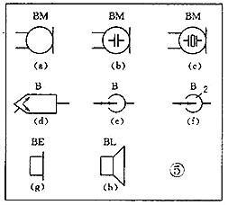
Figure6: Symbols for microphones, pickups, and recording heads
Pickups are commonly known as phono heads. The (d) in Figure ⑤ is the graphic symbol of the stereo cartridge, and its text symbol is "B";
Figure ⑤(e) is the graphic symbol of the monophonic recording and playback head. If there is a two-channel stereo, add a "2" to the symbol, see picture (f).
Ⅵ Symbol for Speakers, Headphones
Speakers and headphones are transducers that convert electrical signals into sound. The symbol of the earphone is shown in Figure ⑤ (g). Its text symbol is "B E". The symbol of the loudspeaker is Figure ⑤ (h), and its text symbol is "BL".
Ⅶ Symbols for wiring elements
In electronic circuits, switching on, off, or switch circuits are necessary. At this time, the wiring components are working. There are two types of wiring components: one is a switch; the other is a connector.
7.1. Switch symbols
In an electromechanical switch, there is at least one moving contact and one stationary contact. When we pull, push, or rotate the mechanism of the switch by hand, the moving contact and the static contact can be connected or disconnected to achieve the purpose of connecting or disconnecting the circuit.
There are generally three types of combinations of moving contacts and static contacts:
- Moving close (normally open) contact, the symbol is in Figure ⑥(a);
- Break (normally closed) contact, the symbol is in Figure ⑥(b);
- Movable change (conversion) contact, the symbol is shown in Figure ⑥(c).
The simplest switch has only one set of contacts, while more complex switches have several sets of contacts.
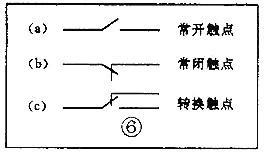
Figure7: Switch symbols
The graphic symbols of the switch in the circuit diagram are shown in Figure ⑦:
(a) indicates a general manual switch;
(b) Indicates a push button switch with a movable contact;
(c) Indicates a push-pull switch with a set of conversion contacts; in the figure, the toggle key is drawn below the contacts to indicate the push-pull action;
(d) means a rotary switch with 3-pole simultaneously moving contacts;
(e) indicates a push-pull 1×6 band switch;
(f) Symbol representing a rotary 1×6 band switch.
Use "S" for the text symbol of the switch, "SA" for the control switch and band switch, and "SB" for the button switch.
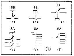
Figure8: Switch symbols
7.2 Connector Symbol
See Figure ⑧ for the graphic symbol of the connector:
(a) Represents a plug and a socket, (there are two representations) the left represents the socket, and the right represents the plug;
(b) means a plug inserted into a socket;
(c) shows a 2-pole socket, also known as a 2-pin socket;
(d) indicates a 3-pole plug socket, which is a commonly used 3-core stereo headphone socket;
(e) means a 6-pole socket;
In order to simplify, it can be represented by Figure (f), and the number 6 is marked on the top of the symbol, indicating that it is 6 poles. The text symbol for the connector is X. In order to distinguish, "XP" can be used to indicate the plug, and "XS" can be used to indicate the socket.
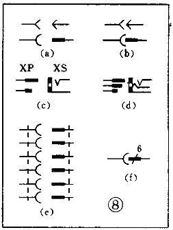
Figure9: Connector Symbol
Ⅷ Relay Symbol
Because the relay is composed of two parts, the coil and the contact group, the graphic symbol of the relay in the circuit diagram also includes two parts: a long box represents the coil; a group of contact symbols represents the contact combination... When the circuit with few contacts is relatively simple, the contact group is often drawn directly on one side of the coil frame. This method of drawing is called centralized representation, as shown in Figure ⑨(a). When there are many contacts and the circuits controlled by each pair of contacts are different. For convenience, decentralized representation is often used. It is to draw the coil in the control circuit and draw the contacts in each controlled circuit according to their respective working objects. This drawing method is beneficial for simplifying and analyzing the circuit. But this has to mark the number of the relay and contacts which is next to each pair of contacts and stipulate that all contacts should be drawn by the original state of the relay not being energized. Figure ⑨(b) is a touch switch. When the human hand touches the metal piece A, the 555-time base circuit outputs (terminal 3) a high potential, which energizes the relay KR1, and the contact is closed to lighten the lamp and sound the bell. The 555-time base circuit is the control part, which uses 6 volts of low voltage. The lights and bell are controlled and run on 220-volt mains electricity.

Figure10: Relay Symbol
The text symbol of the relay is "K". Sometimes, It will use "KA" for AC relays to distinguish. "KR" for electromagnetic relays and reed relays and "KT" for time relays.
Ⅸ Battery and Fuse Symbols
The graphic symbol of the battery is shown in Figure ⑩ (a). The long line represents the positive pole, and the short line represents the negative pole. Sometimes the short line can be drawn thicker for emphasis; Figure ⑩(b) shows a battery pack. Sometimes the battery pack can also be simplified as a battery, but the voltage or the number of batteries should be noted beside it; Figure ⑩(c) is the graphic symbol of the photocell. The text symbol of the battery is "GB". The graphic symbol of the fuse is shown in Figure 11, and its text symbol is "FU".
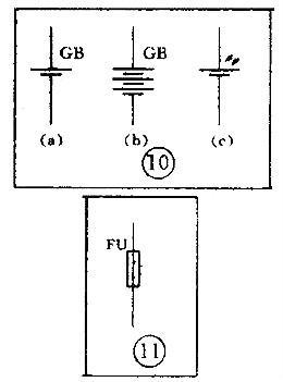
Figure11: Battery and Fuse Symbols
Ⅹ Symbols of Diode and Triode
The graphic symbols of semiconductor diodes in the circuit diagram are shown in Figure 13:
(a): the symbol of a diode. The direction pointed by the arrow is the direction of current flow, that is to say, when the upper end of the diode is connected to a positive voltage and the lower end is connected to a negative voltage, it can be turned on;
(b): the symbol of the Zener diode;
(c): a varactor diode symbol and the capacitor symbol next to it indicates that its junction capacitance changes with the voltage across the diode;
(d): the thermal diode symbol;
(e) means a light-emitting diode symbol, with two obliquely radiating arrows indicating that it can emit light;
(f): the symbol of a magnetic-sensitive diode, which can respond to an external magnetic field and is considered a proximity switch for automatic control.
The text symbol of the diode is "V", sometimes to distinguish it from the triode, it may also be represented by "VD".
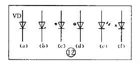
Figure12: Symbols of and Diode and Triode
Since PNP and NPN transistors have different requirements for the polarity of the power supply when they are used, they should be able to be distinguished and represented in the graphic symbol of the transistor.
The standard for graphic symbols: as long as it is a PNP transistor, no matter if it is made of germanium or silicon, it is represented by Figure 13 (a);
Similarly, as long as it is an NPN transistor, regardless of whether it is made of germanium or silicon, it is shown in Figure 13(b);
Figure 13(c) is the symbol of the phototransistor;
Figure 13(d) shows a silicon NPN magnet transistor.
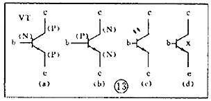
Figure13: Symbols of and Diode and Triode
Ⅺ Symbols for Thyristors, Unijunction Transistors, and Field Effect Transistors
A thyristor is the abbreviation of thyristor or silicon-controlled rectifier. The commonly used ones are unidirectional thyristor, bidirectional thyristor, and light-controlled thyristor. Their symbols are (a) (b) (c) in Figure 14, respectively. The text symbol for thyristor is "VS".
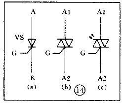
Figure14: Symbols for Thyristors, Unijunction Transistors, and Field Effect Transistors
The symbol of the unijunction transistor is shown in Figure 15
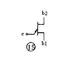
Figure15: The symbol of the unijunction
A semiconductor device controlled by an electric field is called a field effect transistor and its symbol is shown in Figure 16.
Among them, (a) represents an N-channel junction field effect transistor, (b) represents an N-channel enhancement type insulated gate field effect transistor, and (c) represents a P-channel depletion type insulated gate field effect transistor.
Their text notation is also " VT ".
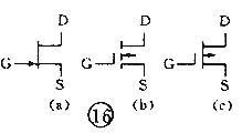
Figure16: a field effect transistor
 Tesla cuts 10% of global layoffs, Samsung increases NAND flash memory production this quarter4/17/2024 22
1.Tesla announced 10% of its global layoffs, with a higher domestic proportion
Read More > How much do you know about fpga design engineer?4/16/2024 34
Circuitry can be a complex field. The circuit must be completely redone because even the smallest error can drastically alter the project's outcome. One of the numerous individuals involved in circuit building is the FPGA design engineer.An electrical engineer with a focus on designing Field Programmable Gate Array integrated circuits is known as an FPGA engineer.After reading this site, you will be fully informed about fpga design engineers.
Read More > Renesas starts up old factory to increase power device production4/15/2024 19
Renesas Electronics announced in December that the Kofu factory that had previously ceased operations was reactivated. As a 300mm wafer fab, the plant will begin mass production of IGBTs and other products in 2025, doubling Renesas' current power semiconductor production capacity. Renesas held an opening ceremony on April 11, which was attended by local government officials and partner companies.
Read More >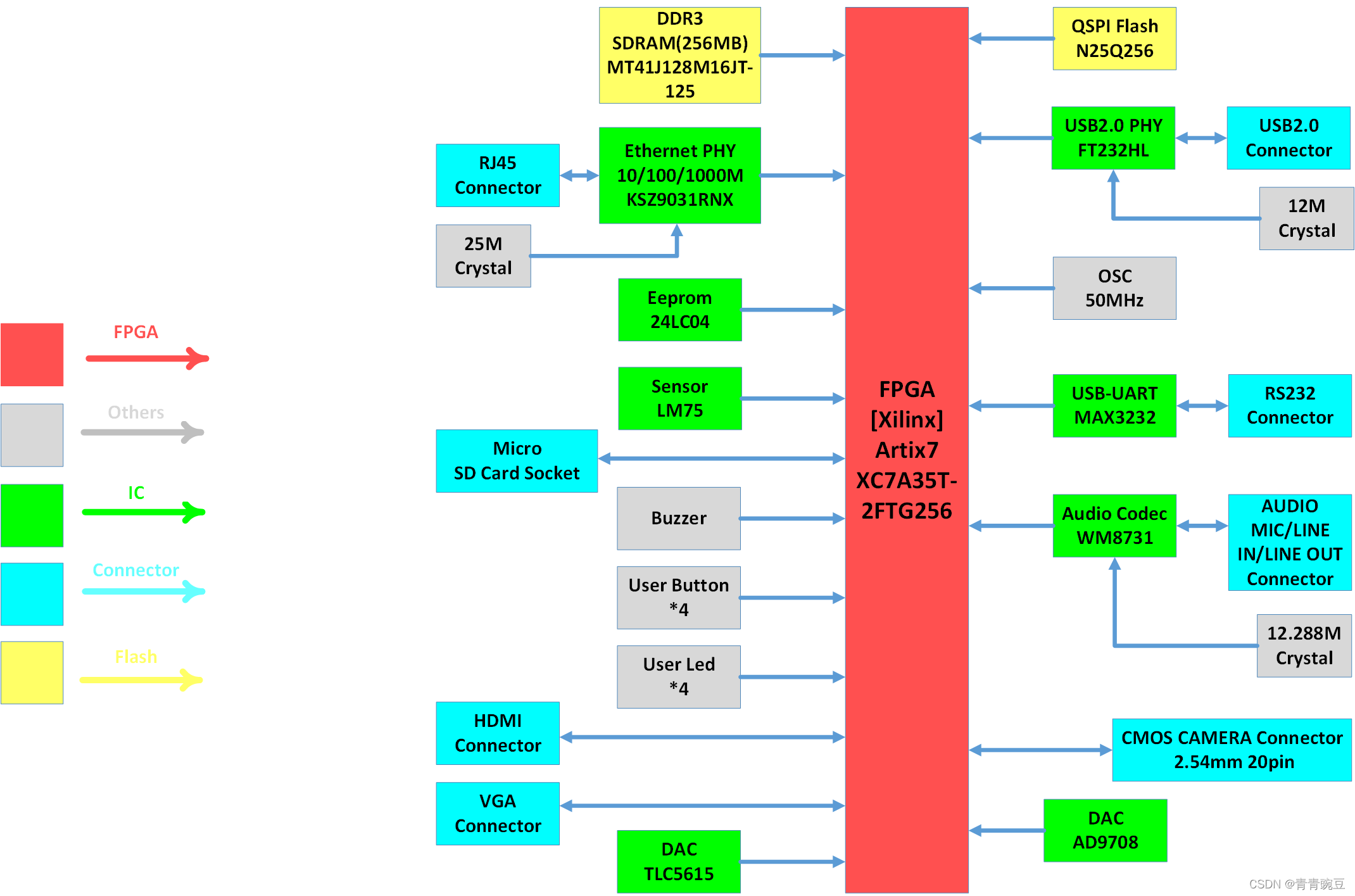 5 key points of Xilinx Artix7 hardware design4/12/2024 32
The following mainly discusses four aspects of the Artix7 chip based on experiences: main chip power supply circuit, selection of main chip filtering capacitors, bank voltage and pin configuration, peripheral circuit construction, and PCB hardware design. These are all summaries obtained after practice, hoping to inspire and help others in their work and study.
Read More > Microchip enabling capacity at TSMC's Kumamoto factory, causing a price increase for Micron products4/11/2024 36
Microchip expands cooperation with TSMC and will establish a 40-nanometer production line at the Kumamoto factory
Read More >
Hot News
- Diode Overview: Application in Automotive Alternator Rectifiers
- Ultra-low power consumption of STM32U575/585 microcontrollers(MCU)
- The Best Guide to Transistor
- Basic Information about Temperature Sensor
- Electronic Component Symbols: Resistor, Capacitor, Transformers and Connectors
- Voltage-Controlled Oscillator: Principle, Type Selection, and Application
SUPPORT
ABOUT BITFOIC
QUICK LINKS
Connect with us
Tel: 86-755-23606554
E-mail: contact@bitfoic.com
Address: Room A29, 24 / F, Hoi Tak Wai, Prince Edward industrial building, 706 Prince Edward Road East, San Po Kong, Kowloon,Hongkong
Mon-Fri: 09.30 AM - 18.30 PM


