


What is LM317 Voltage Regulator: Pinout, CAD model, Circuit Examples and Applications
Introduction
Voltage regulators are electrical or electronic devices that are used to regulate the voltage in a power supply system. Voltage regulators come in a variety of designs, including fixed and variable voltage regulators. Again, these are classified into a wide variety of sorts, including electronic voltage regulators, electromechanical voltage regulators, automatic voltage regulators, linear voltage regulators, switching regulators, LM317 voltage regulators, hybrid regulators, SCR regulators, and others.
Catalog
The LM317 is a three-terminal adjustable voltage regulator, a positive linear regulator for voltage regulation. The LM317 is very easy to use because setting the output voltage requires only two external circuits in the LM317 regulator circuit.
The LM317 is mainly used for local and on-card regulation, if we connect a fixed resistor between the output of the LM317 regulator and the regulation, then the LM317 circuit can be used as a precision current regulator.
LM317 Adjustable Voltage Regulator Tutorial
Ⅱ LM317 Pinout
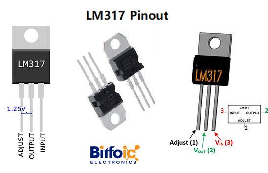
Figure2-lm317 pinout
|
Pin Number |
Pin Name |
Description |
|
1 |
Adjust |
This pin adjusts the output voltage |
|
2 |
Output Voltage (Vout) |
The regulated output voltage set by the adjusted pin can be obtained from this pin |
|
3 |
Input Voltage (Vin) |
The input voltage which has to be regulated is given to this pin |
Looking at the front of a voltage regulator, the first pin (on the left) is the control pin, the middle is Vout, and the last pin (on the right) is Vin.
- Vin
Vin is the pin that receives an input voltage that will be regulated to a specified voltage. For example, the input voltage pin can be fed 12V and the regulator will regulate it to 10V. The input pin receives an input unregulated voltage.
- Control
The control pin (Adj) is the pin that allows control of the voltage output. To adjust the output, we change the value of resistor R2 to a different resistor. This produces an adjustable voltage.
- Vout
Vout is the pin that outputs the regulated voltage. For example, LM317 can receive 12V as input and output a constant 10V as output.
Ⅲ LM317 CAD Model
1、LM317 symbol

Figure3-LM317 symbol
2、LM317 footprint

Figure4-LM317 footprint
3、LM317 3D model

Figure5-LM317 3d model
Ⅳ LM317 Features
- Adjustable 3-terminal positive voltage regulator
- The output voltage can be set to range from 1.25V to 37V
- Output current is 1.5A
- Maximum Input output voltage difference is 40V, recommended 15V
- Maximum output current when a voltage difference is 15V is 2.2A
- The operating junction temperature is 125°C
- Available in To-220, SOT223, TO263 Package

Figure6-Lm317 characteristics
Ⅴ LM317 Working Principle
In the picture below, you can see that we connect two resistors to the voltage regulator, these resistors determine the voltage that the voltage regulator adjusts and outputs.

Figure7-LM317 working principle
The voltage at the output of the adjustable regulator is determined by:
Therefore, according to this formula, it can be seen that the greater the resistance of resistor R2, the greater the output voltage.
In our current setup, these are the values we will be using. We will feed 12V into the regulator and regulate it to 5V.
According to the above formula, for the LM317 to output 5 volts, the value of R2 must be 720Ω. Set up the above circuit, then use a multimeter to check the output voltage by placing it across a 1µF capacitor or resistor and you will find that it is very close to 5 V.
Now replace the R2 resistor and put a 1.5KΩ resistor in its place, the voltage output should now be close to 10V.
This is the beauty of an adjustable voltage regulator, you can adjust it to any voltage within the range supported by the voltage regulator.
NOTE: Capacitors C1 and C2 are used to clear the power lines. C1 is optional and is used to clean up the transient response. C2 is required if the device is far from any filter capacitors, which helps smooth the power line in case of sudden current spikes.
The picture below is what an LM317 regulator would look like when connected to the circuit so that it provides a constant DC voltage output.

Figure8-DC voltage output
In this circuit, we add a DC voltage supply to the Vin pin of the regulator. This is the pin that again receives the input voltage, then the chip will regulate down, the voltage going into this pin must be greater than the voltage it's outputting. Remember that a voltage regulator is just a device that regulates voltage to a certain level, but does not and cannot generate voltage on its own. Therefore, to get a voltage Vout, Vin must be greater than Vout.
In this circuit, we need a stable 5VDC as output, therefore, Vin must be greater than 5V. Generally, with regulators, unless they are low dropout regulators, you want the input voltage to be about 2 V higher, so with 5 V as output, we'll be feeding 7 V to that regulator.
Now that the input pins have been dealt with, let's move on to the adjustable pin (Adj). Since you want to output 5V, you must calculate which value of R2 will produce a 5V output.
Using the output voltage formula:
Vout = 1.25V (1 + R2/R1)
Since R1=240Ω, so: 5V=1.25V (1 + R2/240Ω), so R2=720Ω.
Therefore, when the value of R2 is 720Ω, if the input voltage is greater than 5V, the LM317 will output 5V.
The last pin of the LM317 is the output pin, in order to provide the regulated 5 volts to the circuit we just need to connect it to the output pin.
Ⅵ How to Use LM317?
The LM317 component develops and regulates 1.25V between the output and adjust pins, you can change the output using two resistors connected between the output and input pins.
In addition, two decoupling capacitors can be connected to one circuit, and this integration eliminates unnecessary coupling while preventing noise.
Also, a 1µF capacitor is connected to the output to improve transient response. You can then make it work as a variable regulator by clicking the potentiometer on the adjustable pin.
Resistors and potentials work together to create a potential difference that regulates the output.
Ⅶ LM317 Voltage Regulator Circuit
The input pin, output pin, and adjustment pin are the three terminals. A common arrangement of the LM317 voltage regulator circuit diagram, including the decoupling capacitors, is depicted in the figure below. This LM317 circuit has a 1A output and a 30V range of adjustment, and it can offer variable DC power. A resistive voltage divider, a passive linear circuit used to generate an output voltage that is a portion of its input voltage, is created by connecting a low-side resistor and a high-side resistor in series.
Decoupling capacitors are used to decouple electrical circuit components from one another or to stop this from happening. The decoupling capacitors in the circuit are utilized for addressing the input noise and output transients in order to prevent the effect of noise created by some circuit parts over the remaining circuit elements. The circuit uses a heat sink to prevent overheating of the components from increased power dissipation.

Figure9-Decoupling capacitors
7.1 Features
There are some special features of the LM317 regulator and a few are as follows:
- It is capable of providing an excess current of 1.5A, hence it is conceptually considered as an operational amplifier with an output voltage ranging from 1.2V to 37V.
- The LM317 voltage regulator circuit internally consists of thermal overload protection and short circuit current limiting constant with temperature.
- It is available in two packages as 3-Lead Transistor Package and surface mount D2PAK-3.
- Stocking many fixed voltages can be eliminated.
7.2 Working of Voltage Regulator LM317 Circuit
Due to its capacity to produce excess output current, the LM317 regulator is conceptually regarded as an operational amplifier. The non-inverting input of the amplifier is set using an internal bandgap reference voltage, and the adjustment pin serves as the amplifier's inverting input. This produces a stable reference voltage of 1.25V.
The output pin voltage can be continuously adjusted to a fixed amount using a resistive voltage divider between the output and ground, which will configure the operational amplifier as a non-inverting amplifier.
A bandgap reference voltage is used to produce constant output voltage irrespective of the changes in supply power. It is also called a temperature-independent reference voltage frequently used in integrated circuits.
The output voltage (ideally) of the LM317 voltage regulator circuit
Vout = Vref * (1+ (RL/RH))
An error term is added because some quiescent current flows from the adjustment pin of the device.
Vout = Vref * (1+(RL/RH)) + IQR
For achieving more stable output, the LM317 voltage regulator circuit diagram is designed such that to make the quiescent current less than or equal to 100 micro Amperes. Thus, in all practical cases, the error can be ignored.
Ⅷ LM317 Alternative Model
LM317 alternative models: LM7805, LM7806, LM7809, LM7812, LM7905, LM7912, LM117V33, XC6206P332MR.
LM317 Equivalent; LT1086, LM1117 (SMD), PB137, LM337 (Negative Variable Voltage Regulators)
Ⅸ How to Protect the LM317 circuit?
Components may overheat due to more power dissipation. For this reason, heat sinks are used to protect the IC from overheating. Due to the low current of the regulator, the external capacitor can discharge. Therefore, in some applications, protection diodes are added to prevent capacitor discharge.
Diode D1 protects the capacitor from discharging during an input short circuit, while diode D2 is used to protect CAdj by providing a low-impedance discharge path during an output short circuit. To achieve a high ripple rejection ratio, bypass the ADJUST terminal.

Figure10-How to protect LM317 circuit
Ⅹ LM317 as a USB Battery Replacement
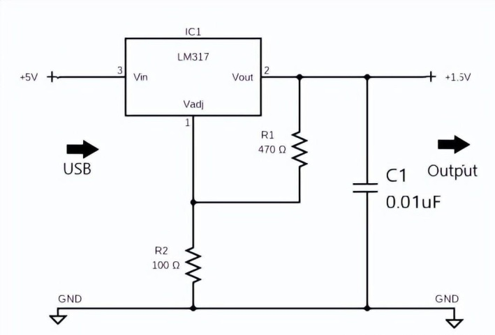
Figure11-LM317 as a USB battery replacement
You can also use this USB battery replacement circuit as a power source, it typically steps down the 5V input voltage (USB port) to 1.5V/1.5A max output.
The whole thing goes through an LM317 DC regulator and it also performs well with 3V results. Additionally, the circuit has two resistors to adjust the output voltage of the LM317 via the adjust pin. One resistor (R 1 ) is rated at 470 ohms and the second resistor (R 2 ) is rated at 100 ohms.
Overall, the circuit can be used as a battery replacement to power USB-compatible electronics. For example, if the battery dies, you can plug your music player into it to listen to some music.
Ⅺ LM317 Circuits Examples
Variable DC Power Supply Using LM317
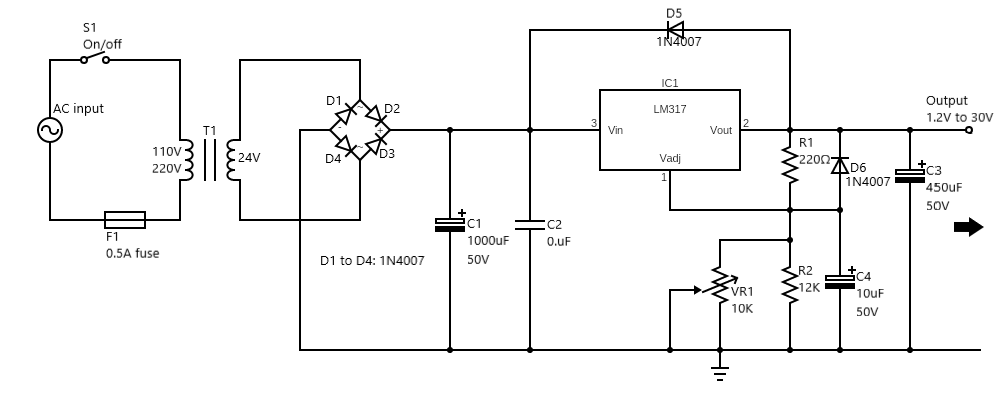
Figure12-Circuit diagram of a variable DC power supply
Using the LM317 variable DC power supply typically allows the user to adjust the voltage and 1A of current from 1.25V to 30V. It runs as a power source instead of a 1.5V AA battery.
The transformer (T1) reduces the current from AC 220V to AC 24V. Afterward, it is distributed to the bridge diode rectifiers D1 to D4, and the filter capacitor C1 stores a rated voltage of DC 35V. At the same time, the adjust pin of IC1 adjusts the output voltage for VR1. VR1 then controls the DC voltage from 1.25V to a maximum of 37 at 30V or 1.5A.
Nicad Battery Charger using LM317

Figure13-NiCAD battery charger circuit diagram with the LM317
The NiCd battery charger circuit using the LM317T allows charging of 2.4V, 4.8V, and 9.6V NiCd batteries. The secondary winding of the transformer is set to 9V/300mA. Meanwhile, the 220uF 25V capacitor acts as a filter to smooth the voltage, and the voltage regulator circuit adjusts the voltage of each battery level.
Ⅻ LM317 Applications
- Voltage step-down circuits
- Lab power supplies
- Battery Chargers
- Solar Power Supplies
- Microcontroller Related Applications
- DC to DC converters
- Portable Instruments
 CR2025 vs CR2016: Which one you should choose ?5/8/2024 26
CR2025 is a type of lithium coin cell battery. It's a small, round, flat battery commonly used in various electronic devices such as watches, calculators, remote controls, key fobs, and small electronic gadgets. The "CR" in its name stands for lithium manganese dioxide chemistry, and "2025" refers to its dimensions: 20mm diameter and 2.5mm height. These batteries are known for their long shelf life and stable voltage output, making them popular choices for low-power devices.
Read More >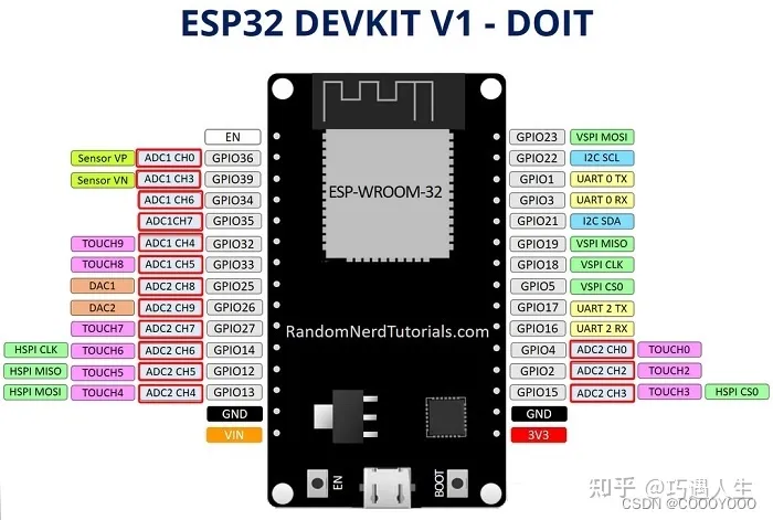 How to resolve the WiFi and ADC2 Sharing Dilemma?4/19/2024 47
ESP32-CAM can be used in various Internet of Things situations and is suitable for home smart devices, industrial wireless control, wireless Monitoring, QR wireless identification, wireless positioning system signals, and other IoT applications are ideal solutions for IoT applications.
Read More >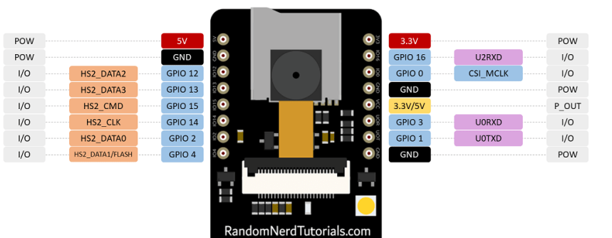 ESP32-CAM Pinout Explanation and How to Use?4/18/2024 131
ESP32-CAM is a development board with an ESP32-S chip, an OV2640 camera, a microSD card slot, and several GPIOs for connecting peripherals. ESP32-CAM is a small-sized camera module. The module can work independently as the smallest system, with a size of only 27*40.5*4.5mm.
Read More > Stand-Alone Linear Li-Ion / Li-Polymer Charge Management Controller MCP738334/9/2024 70
The MCP73833/4 is a highly advanced linear charge management controller for use in space-limited, cost sensitive applications. Both a 10-lead, MSOP and a 10-lead, DFN packaging measuring 3 mm by 3 mm are offered for the MCP73833/4. In addition to its tiny size, the MCP73833/4 is perfect for portable applications because it requires a few additional components.
Read More >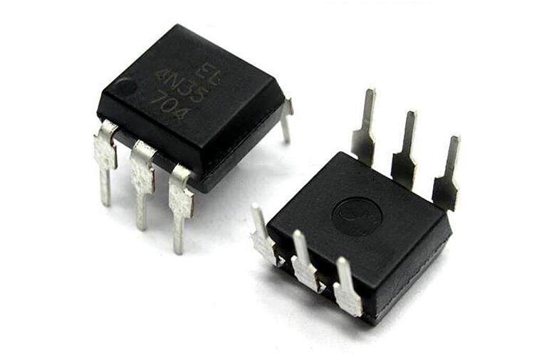 Optocoupler IC 4N35: Pinout, Datasheet, Features and Applications3/26/2024 129
In the realm of electronics, where connectivity and isolation are paramount, the 4N35 optocoupler IC stands as a beacon of reliability and versatility. This small yet mighty device plays a crucial role in ensuring signal integrity and safety across a wide range of applications. In this article, we delve into the intricacies of the 4N35 optocoupler IC, exploring its datasheet, pinout, circuit diagram, and diverse uses.
Read More >
SUPPORT
ABOUT BITFOIC
QUICK LINKS
Connect with us
Tel: 86-755-23606554
E-mail: [email protected]
Address: Room A29, 24 / F, Hoi Tak Wai, Prince Edward industrial building, 706 Prince Edward Road East, San Po Kong, Kowloon,Hongkong
Mon-Fri: 09.30 AM - 18.30 PM


