


ESP32-CAM Pinout Explanation and How to Use?
Introduction
WiFi is one of the core functions of ESP32. As a chip specially designed for IoT, ESP32's WiFi function is very complete. It can be used as AP, STA, or both STA and AP simultaneously. In this guide, we will learn about ESP32-CAM Pinout and how to solve WIFI cannot be shared with ADC2 on the ESP32-CAM board.
Table of Content
|
ESP32-CAM Pinout Explanation and how to use GPIO 0 pin – Flash Mode Selection |
What is ESP32-CAM?
ESP32-CAM is a development board with an ESP32-S chip, an OV2640 camera, a microSD card slot, and several GPIOs for connecting peripherals. ESP32-CAM is a small-sized camera module. The module can work independently as the smallest system, with a size of only 27*40.5*4.5mm.
ESP32-CAM Schematics

Figure1-ESP32-CAM Schematics
ESP32-CAM Features
Using a low-power dual-core 32-bit CPU as an application processor
- Main frequency up to 240MHz, computing power up to 600 DMIPS
- Built-in 520 KB SRAM, external 8MB PSRAM
- Support UART/SPI/I2C/PWM/ADC/DAC and other interfaces
- Supports OV2640 and OV7670 cameras with built-in flash
- Support image WiFI upload
- Support TF card
- Multiple sleep modes compatibility.
- Lwip and FreeRTOS built-in
- Support STA/AP/STA+AP working mode
- Supports Smart Config/AirKiss one-click network configuration
- Support secondary development
ESP32-CAM Pinout Explanation and how to use?
ESP32-CAM is a full-featured microcontroller that has a video camera as well. To understand the functioning of a microcontroller, it is necessary to understand its pinouts and connections before use. So, the pinout structure of the ESP32-CAM is as follows:
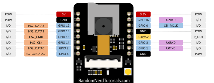
Figure2- ESP32-CAM Pinout

Figure3- ESP32-CAM
The ESP32-S chip has a total of 32 pins but many of them are internally used, so there are only 16 pins exposed to the pinout header which are available for ESP32-CAM.
Power Pins
ESP32-CAM is equipped with three GND pins (black) and two power pins (red): 3.3V and 5V. You can pass a 3.3V or 5V pin. However, many people have reported errors when supplying 3.3V to the ESP32-CAM, so we always recommend powering the ESP32-CAM via the 5V pin.
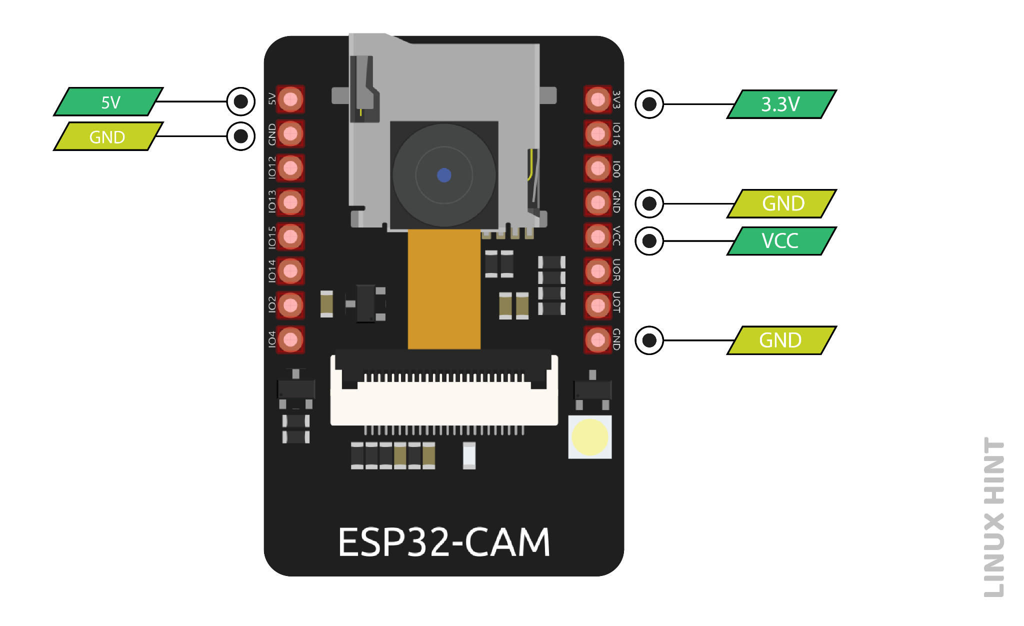
Figure4-Power Pins
Power output pin
The pins on the silkscreen are also marked VCC (colored with a yellow rectangle). You should not use this pin to power the ESP32-CAM. This is an output power pin. It can output 5V or 3.3V. In our case, the ESP32-CAM outputs 3.3V, whether powered by 5V or 3.3V. Next to the VCC pin, there are two solder pads. One is marked 3.3V and the other is marked 5V. If you look closely you should have a jumper on the 3.3V pad. If you want to have a 5V output on the VCC pin, you need to disconnect that connection and solder the 5V pad.
GPIO Pin
GPIO 1 and GPIO 3 are serial pins (TX and RX respectively). Since the ESP32-CAM does not have a built-in programmer, you will need to use these pins to communicate with the board and upload code.
The best way to upload code to ESP32-CAM is to use the FTDI programmer.
GPIO 1 and GPIO 3 can be used to connect other peripherals like outputs or sensors after uploading the code. However, you won't be able to open the serial monitor and see if everything is fine with your setup.
GPIO 0 pin – Flash Mode Selection
GPIO 0 determines whether the ESP32 is in flash mode. This GPIO is internally connected to a pull-up 10k ohm resistor.
When GPIO 0 is connected to GND, the ESP32 will enter flash mode and you can upload code to the development board.
To make the ESP32 run "normally" you just need to disconnect GPIO 0 from GND.
LED(GPIO 4)
ESP32-CAM has a bright built-in LED that can be used as a flash when taking photos. This LED is internally connected to GPIO 4.
This GPIO is also connected to the microSD card slot, so you may have trouble when trying to use both at the same time - the flashlight will come on when using the microSD card.
Note: One of our card readers shared that if you initialize the microSD card as follows, you will not encounter this issue because the microSD card does not use this data line.

Figure5-LED code
We found this works and the LED does not create a flashing effect. However, the LED still lights up at low brightness - we're not sure if we're missing something.
GPIO 33 – Built-in red indicator light
Next to the RST button, there is an onboard red LED. This LED is internally connected to GPIO 33. You can use this LED to indicate that something is happening. For example, if Wi-Fi is connected, the LED is red, and vice versa.
The LED works with inverted logic, so you send a low signal to turn it on, and then a high signal to turn it off.
You can try uploading the following code snippet and see if the LED lights up.
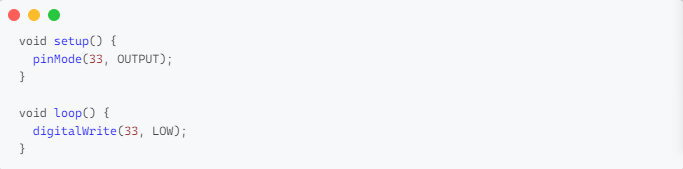
Figure- red indicator light
MicroSD card connection
If you are not using a microSD card, you can use these pins as regular input/output. You can view the characteristics of these pins.
All these GPIOs are RTC and support ADC: GPIO 2, 4, 12, 13, 14 and 15.
|
Micro SD card pins |
ESP32 pins |
|
CLK |
GPIO 14 |
|
CMD |
GPIO 15 |
|
DATA0 |
GPIO 2 |
|
DATA1 / flashlight |
GPIO 4 |
|
DATA2 |
GPIO 12 |
|
DATA3 |
GPIO 13 |
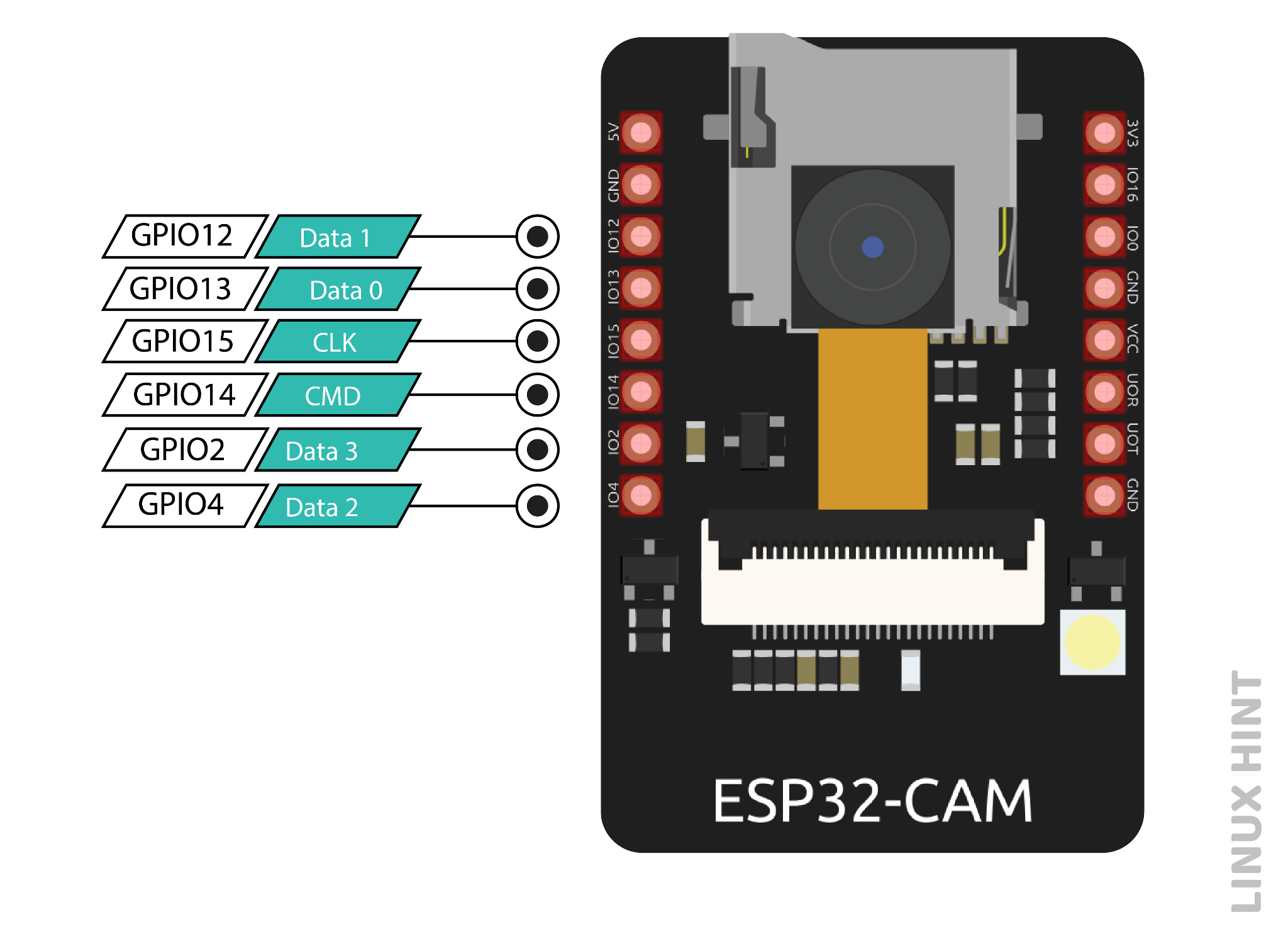
Figure7-MicroSD
ADC pins
The pins of an ADC (Analog Digital converter) can transform analog signals into digital signals. The ADC transforms voltage into a bit that the CPU can comprehend. Due to the 12-bit resolution of the ADC input channel, values can vary from 0 to 4095, where 0 corresponds to 0V and 4095 to 3.3V. When Wi-Fi is turned on, ADC2 pins cannot be accessed since the Wi-Fi driver uses them internally. The ADC2 GPIO does not provide output when Wi-Fi is enabled.
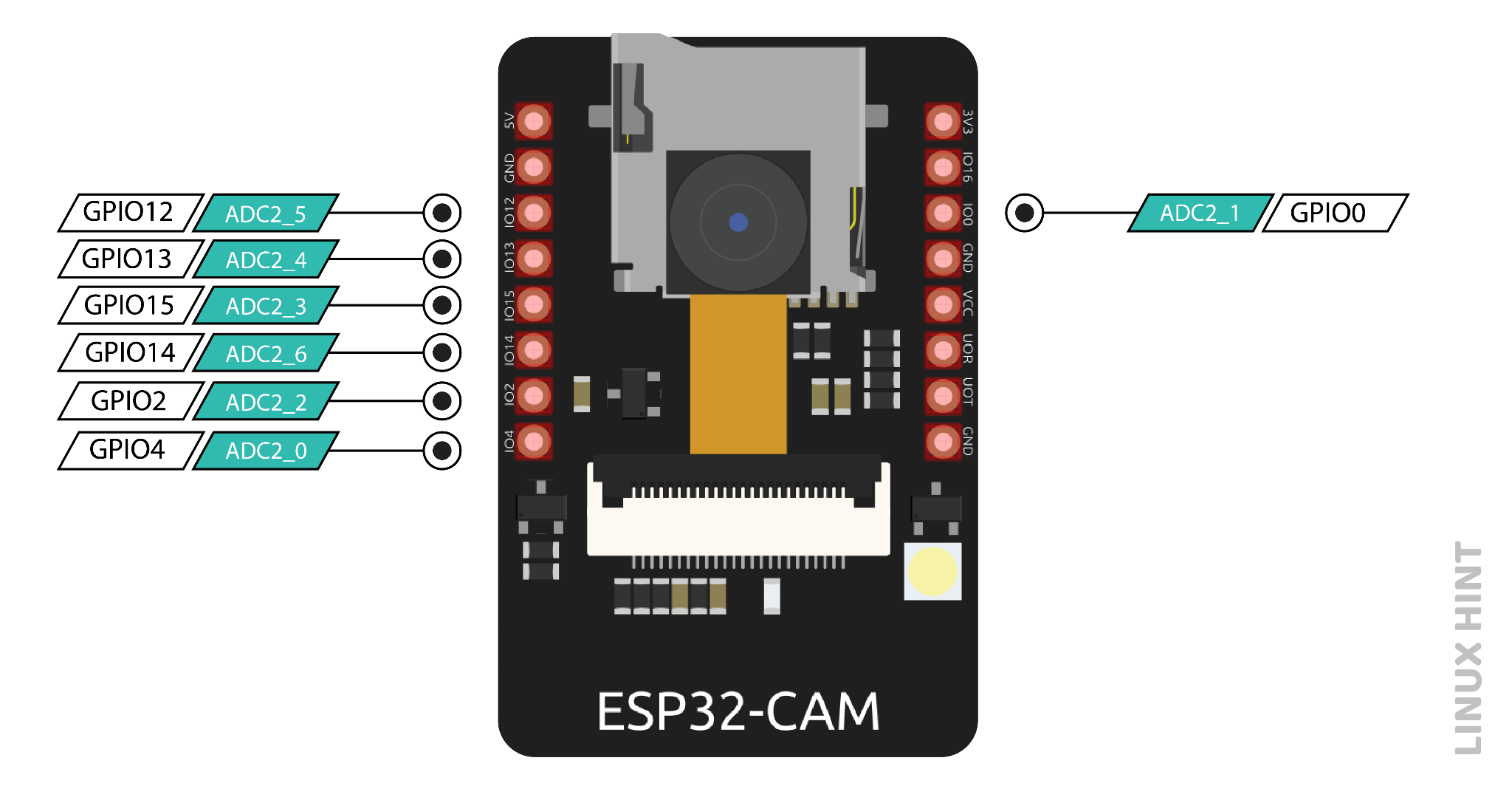
Figure8-ADC pins
RTC GPIO Pins (Interrupt)
An external interruption to the system's regular operation is referred to as an external interruption. The source of this interruption could be the user or any other device connected to the networks. ESP32-CAM interrupts are frequently used to wake the microcontroller up for a task. The GPIO pins in the ESP32-CAM that are indicated below can be set to interrupt modes. These RTC GPIO pins are wired to the low-power subsystem, which wakes the ESP32 from sleep when an ultra-power coprocessor is operating.
SPI pins
A microcontroller can establish a bus-like connection and communicate with one or more external devices using the Serial Peripheral Interrupt (SPI) data transfer protocol. Within SPI communication, a Master and a Slave exist. The slave obeys the master's command once the master determines which task to complete.
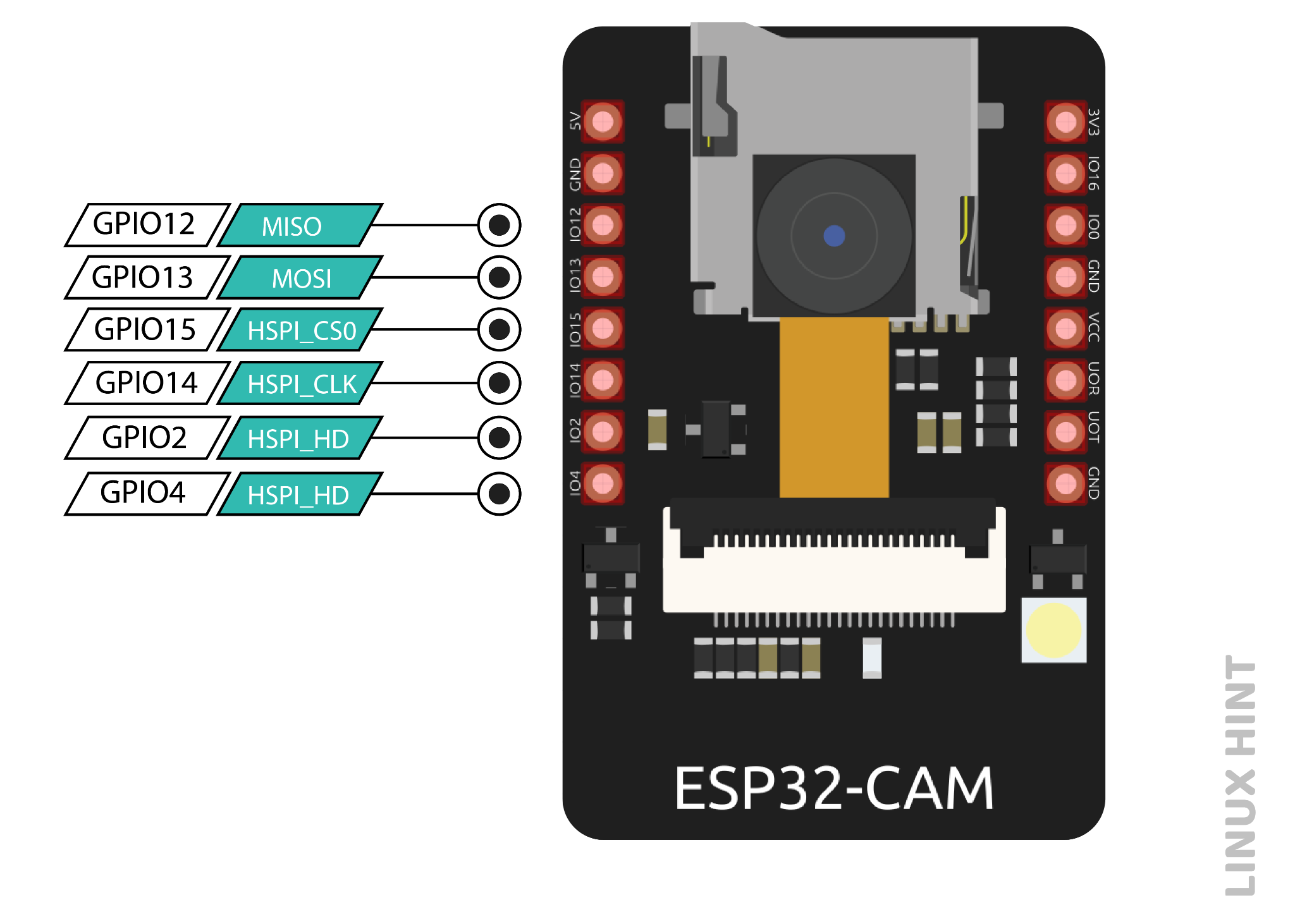
Figure9-SPI pins
| SPI | HSPI |
| MOST | GPIO 13 |
| MISO | GPIO 12 |
| CLK | GPIO 14 |
| CS | GPIO 15 |
MISO: This pin determines which line data is sent to the master device.
MOSI: This pin chooses the master line to use when sending data to the peripheral devices.
SCLK: This pin chooses the clock, which is produced by the master device, to synchronize data transmission.
SS: The slave device is selected using this pin.
Touch Pins
Seven intrinsic capacitive touch sensing GPIOs on the ESP32-CAM allow it to detect changes in charge-containing objects, like human skin. It can feel and detect changes in capacitance when something charged approaches it.
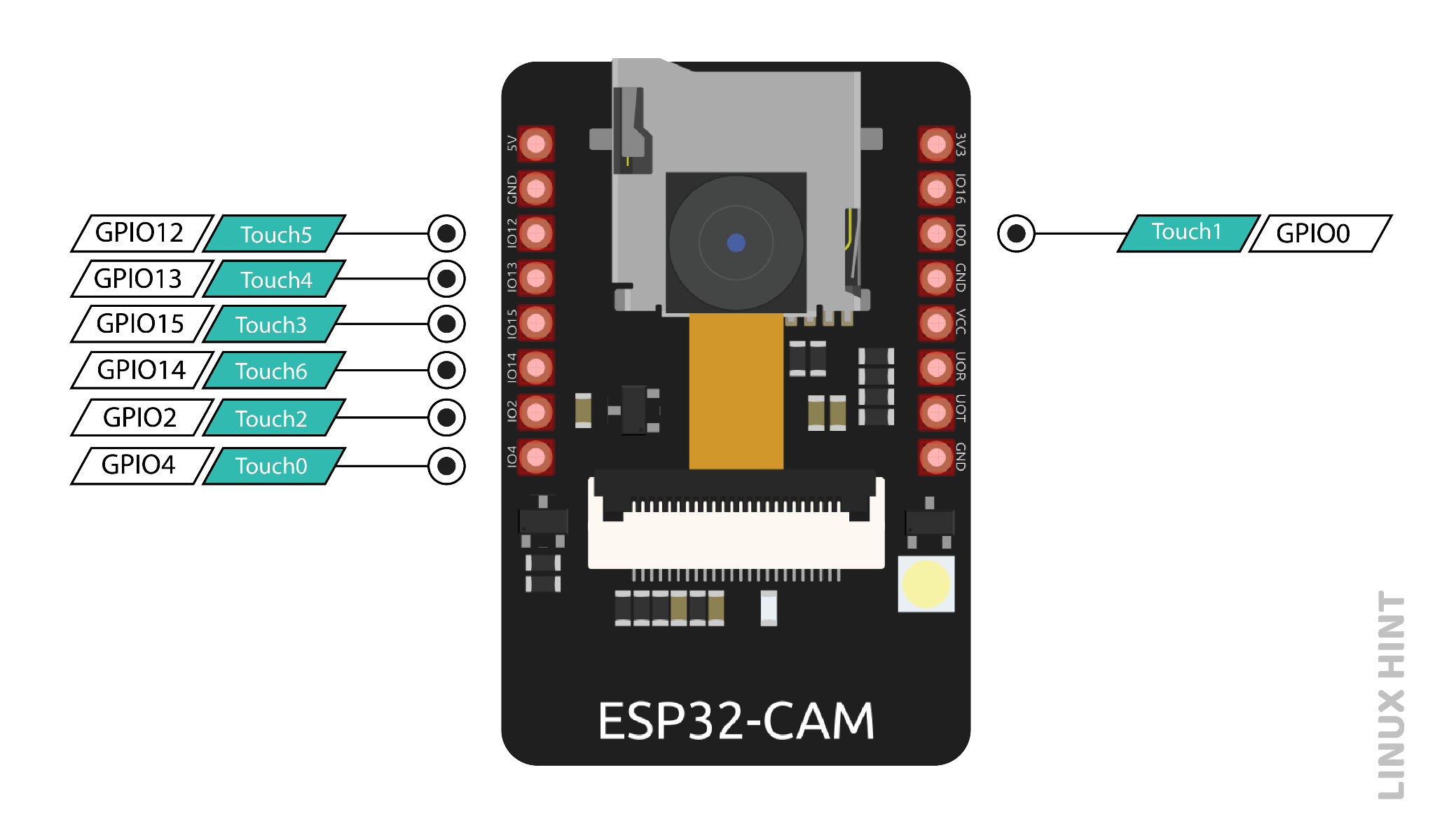
Figure10-Touch Pins
Any conducting material can be attached to these pins to create a capacitive touchpad, which can replace mechanical buttons.
PWM pins
All the 10 GPIOs can be used as PWM pins, and a PWM controller operates them.
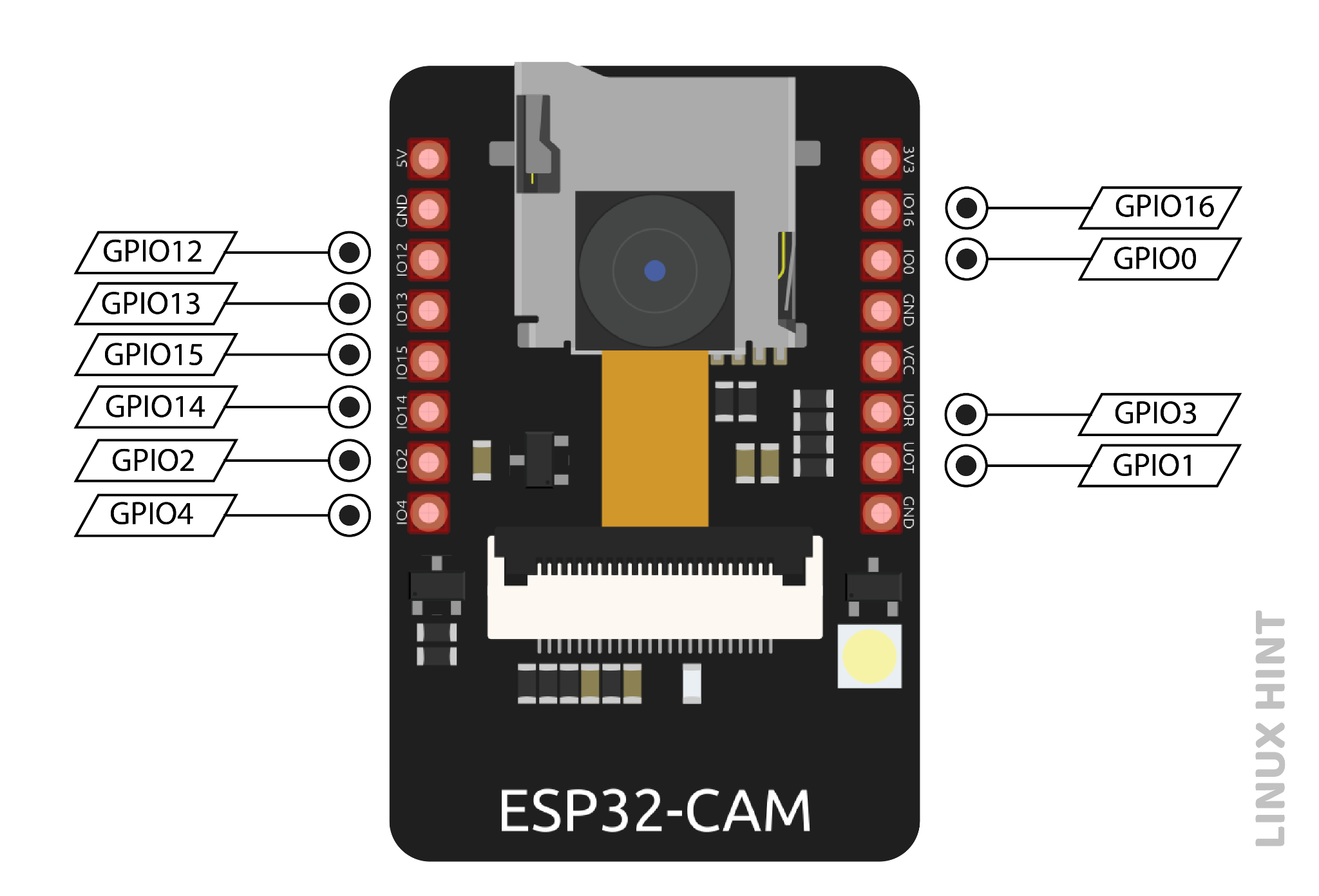
Figure11-PWM pins
PWM timers, a specialized capture submodule, and a PWM operator are features of the PWM controller. The operator creates the channel waveform, the PWM timer produces timing in either synchronous or independent form, and the capture submodule records events using external timing.
Conclusion
ESP32-CAM can be used in various Internet of Things situations and is suitable for home smart devices, industrial wireless control, wireless Monitoring, QR wireless identification, wireless positioning system signals, and other IoT applications are ideal solutions for IoT applications.
 How to resolve the WiFi and ADC2 Sharing Dilemma?4/19/2024 27
ESP32-CAM can be used in various Internet of Things situations and is suitable for home smart devices, industrial wireless control, wireless Monitoring, QR wireless identification, wireless positioning system signals, and other IoT applications are ideal solutions for IoT applications.
Read More >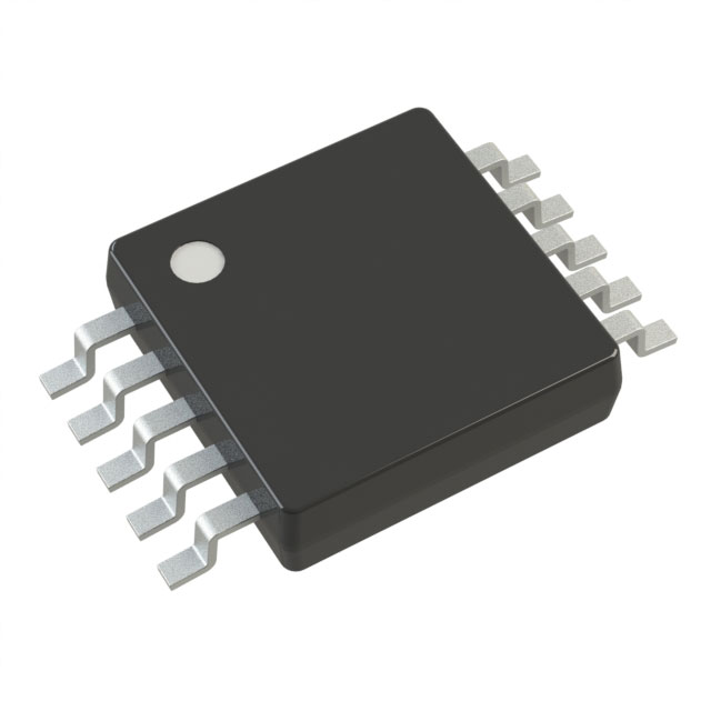 Stand-Alone Linear Li-Ion / Li-Polymer Charge Management Controller MCP738334/9/2024 63
The MCP73833/4 is a highly advanced linear charge management controller for use in space-limited, cost sensitive applications. Both a 10-lead, MSOP and a 10-lead, DFN packaging measuring 3 mm by 3 mm are offered for the MCP73833/4. In addition to its tiny size, the MCP73833/4 is perfect for portable applications because it requires a few additional components.
Read More >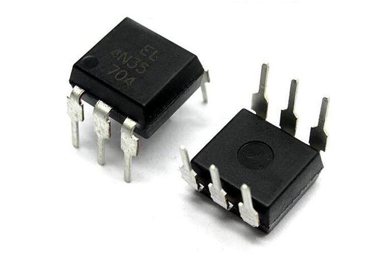 Optocoupler IC 4N35: Pinout, Datasheet, Features and Applications3/26/2024 108
In the realm of electronics, where connectivity and isolation are paramount, the 4N35 optocoupler IC stands as a beacon of reliability and versatility. This small yet mighty device plays a crucial role in ensuring signal integrity and safety across a wide range of applications. In this article, we delve into the intricacies of the 4N35 optocoupler IC, exploring its datasheet, pinout, circuit diagram, and diverse uses.
Read More >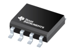 UA741CP datasheet ,Specification, Features and Application3/21/2024 111
The UA741CP is a general-purpose operational amplifier in an 8-pin DIP package. The high common-mode input voltage range and lack of latch-up make the amplifier ideal for voltage follower applications.
Read More >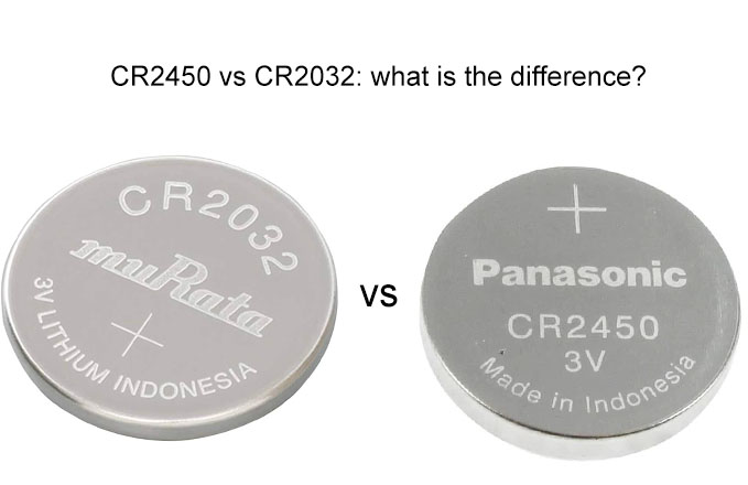 CR2450 vs CR2032: Which model can replace CR2450?3/14/2024 187
Among the various types of batteries available, coin cell batteries are commonly used in small devices like calculators, watches, and key fobs. Two popular types of coin cell batteries are the CR2450 and CR2032. While they may seem similar due to their naming conventions, they have distinct differences that affect their interchangeability and applications.
Read More >
SUPPORT
ABOUT BITFOIC
QUICK LINKS
Connect with us
Tel: 86-755-23606554
E-mail: contact@bitfoic.com
Address: Room A29, 24 / F, Hoi Tak Wai, Prince Edward industrial building, 706 Prince Edward Road East, San Po Kong, Kowloon,Hongkong
Mon-Fri: 09.30 AM - 18.30 PM


