


How to resolve the WiFi and ADC2 Sharing Dilemma?
Why explore this problem?
Due to the needs of the laboratory, I use ESP32cam to collect pictures, videos, and other information and transmit it to the IoT platform. At the same time, I also collect sensor information such as temperature, humidity, and PH value, and transmit it to the IoT platform simultaneously.
Because there is a lot of content, they are tested separately:
Test whether esp32cam connects to wifi and works normally
Test whether the esp32cam picture is collected normally and whether it can be transmitted to the external server through wifi
Test whether esp32cam can collect sensing information such as temperature, humidity, and pH value and output it.
The problem arises at this time. When testing functions 1, 2, and 3 separately, all functions are normal. However, after merging the program, the values collected by the PH sensor are all 0. I always thought that there was a problem with the sensor or an error that occurred during code merging, and I was delayed in these places. It took a long time; later, after consulting a lot of information, I found that it was a problem with the ESP32 development board hardware.
Check relevant information
The PH value sensor is an analog acquisition sensor and needs to be connected to the ADC interface of the ESP32 for digital-to-analog conversion. However, the ESP32 series only has two ADC digital-to-analog converters. When the ESP32 development board is connected to WIFI, WIFI will occupy ADC2, and WIFI The priority of occupying ADC2 is relatively high, and other modules cannot use ADC2 to obtain values, which is why the values collected by the PH sensor are all 0. However, ADC1 is not affected. At this time, you only need to connect the analog sensor to ADC1 for normal use.
Official Github: wifi and ADC2 cannot be used at the same time.
The pin functions of the ADC on the ESP32 development board are defined above (
):
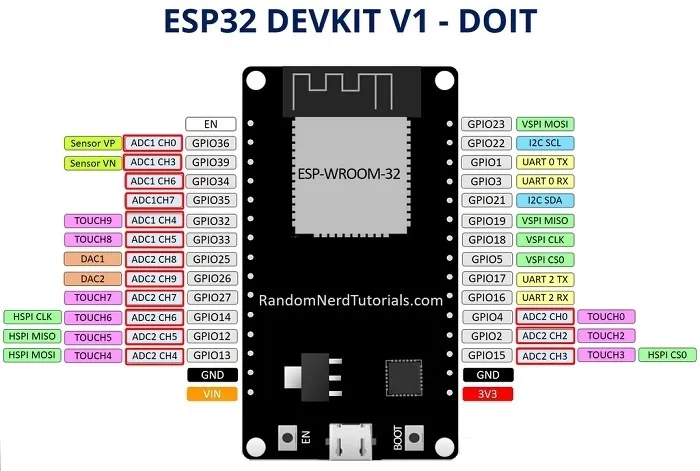
Figure1-ESP32 pinout
But for the ESP32cam development board, this is another difficulty. The ESP32cam development board does not lead to the IO pins of ADC1, and some of the ADC1 pins are occupied by the camera module, so the ADC1 digital-to-analog converter cannot be used normally on the ESP32cam development board. The pin functions of the ADC on the ESP32cam development board are defined as above (
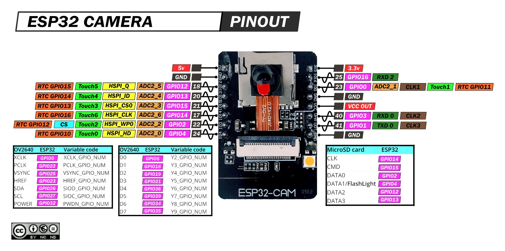
Figure2-ESP32 pinout
A solution to sharing WIFI and ADC2 in ESP32cam
Through the above explanation and various other documents, tutorials, reference materials, etc., it is said that WIFI and ADC2 cannot be shared. But the essence is that WIFI occupies ADC2, causing other analog sensors to be unable to read data through ADC2.
Question: Is it possible to turn off the WIFI function before ESP32 reads the analog sensor data connected to ADC2, turn on the WIFI function after reading the data, and then send the data to the external network platform?
The answer is: Yes, that is, you can use WIFI and ADC2 alternately.
Through actual measurement in the ESP32cam development board, it was found that this can normally read the correct value of the analog signal sensor connected to ADC2, but it will take more time to reconnect to WIFI each time. The time to reconnect to WIFI is variable, about 1 second.
This method can solve the problem of using ADC2 to collect data from analog sensors that do not collect information with high real-time performance. For example, for a PH value sensor, PH value information is collected every 3 minutes or 5 minutes. At this time, the 1 second required to reconnect to WIFI can be ignored for minute-level data collection. However, for analog signal sensors using ADC2 that have high real-time requirements, the 1 second it takes to reconnect to WIFI becomes unacceptable, and this method is useless.
The Arduino code shared by WIFI and ADC2 in ESP32cam is as follows:
#include <Arduino.h>#include <WiFi.h>#include "esp_camera.h"#include <vector>#include <string.h>using namespace std;
// ph and tem Variable settings const int phPin = 2;float Value = 0;
// wifi Account and password const char *ssid = "TP-LINK_1760";const char *password = "987654321";
void wifi_init() {
WiFi.mode(WIFI_STA);
WiFi.setSleep(false); //Turn off wifi sleep in STA mode to improve response speed WiFi.begin(ssid, password);
while (WiFi.status() != WL_CONNECTED) {
delay(500);
Serial.print(".");
}
Serial.println("WiFi Connected!");
Serial.print("IP Address:");
Serial.println(WiFi.localIP());}
void setup() {
Serial.begin(115200);
// wifi initialization wifi_init();
pinMode(phPin, INPUT);}void loop() {
// turn off wifi WiFi.disconnect(true);
WiFi.mode(WIFI_OFF);
// adc2 Read data pinMode(phPin, INPUT);
Value = analogRead(phPin);
// turn on wifi wifi_init();
// Serial port print data Serial.print(Value);
delay(500);}
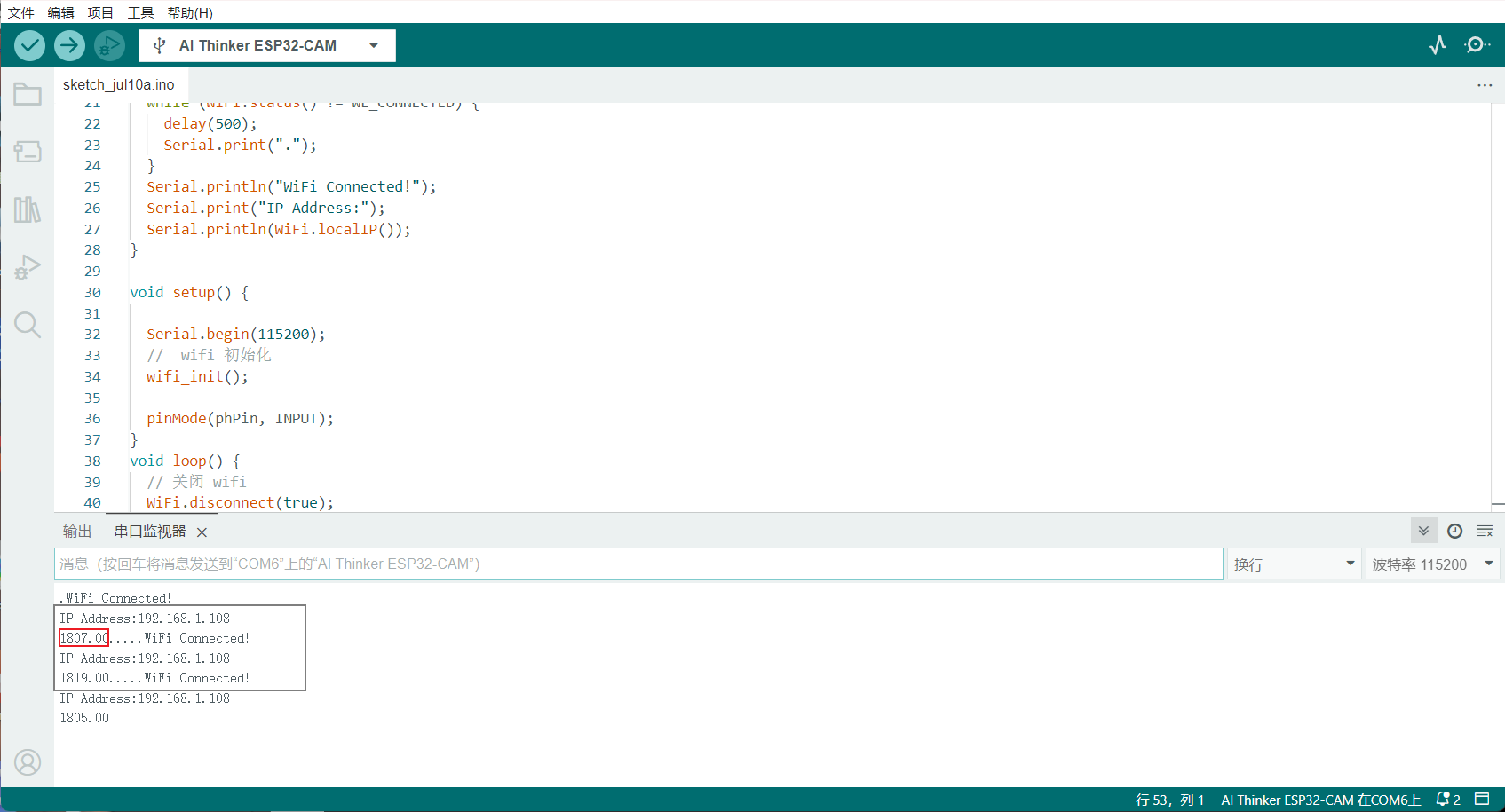
Figure3-code
 DC-DC converter RFB-0505S: Specification,Datasheet,Features and Applications6/13/2024 587
The RFB-0505S is a DC-DC converter from RECOM Power, Inc., belonging to the RFB Series. It features a Single In-Line Package (SIP7) and provides a single unregulated output. This converter offers 1 watt of power with an output voltage of 5V and is rated for an isolation voltage of 1kV.
Read More > Understanding the RFMM-0505S DC-DC Converter: A Comprehensive Guide6/4/2024 763
In the world of electronics, ensuring efficient power management is crucial for the performance and reliability of devices. One of the key components in achieving this is the DC-DC converter. Today, we dive into the specifics of the RFMM-0505S DC-DC converter, exploring its features, applications, and benefits.
Read More > 12V DC-DC Converter AM2G-0512SZ: Specifications, Datasheet, Applications and Features6/3/2024 681
A DC-DC converter is an essential electronic device to convert a direct current (DC) source from one voltage level to another. These converters are widely employed in various applications, including portable electronic devices, automotive systems, and renewable energy installations.
Read More > What is LM3900 Quadruple Norton Operational Amplifier?5/30/2024 1369
The LM3900 consists of four independent dual-input internally compensated amplifiers. These amplifiers are specifically designed to operate on a single power supply voltage and provide a large output voltage swing. They utilize current mirrors to achieve in-phase input functionality. Applications include AC amplifiers, RC active filters, low-frequency triangle waves, square wave, and pulse waveform generation circuits, tachometers, and low-speed, high-voltage digital logic gates.
Read More > Exploring the MMBT3906 Transistor: A Comprehensive Guide5/24/2024 981
The goal of the Taiwan Semiconductor MMBT3906 PNP Bipolar Transistor is to provide a high surge current capability with minimal power loss. This transistor is perfect for automated installation and has high efficiency.
Read More >
SUPPORT
ABOUT BITFOIC
QUICK LINKS
Connect with us
Tel: 86-755-23606554
E-mail: [email protected]
Address: Room A29, 24 / F, Hoi Tak Wai, Prince Edward industrial building, 706 Prince Edward Road East, San Po Kong, Kowloon,Hongkong
Mon-Fri: 09.30 AM - 18.30 PM


