


LM324 Quad Op Amp ICs: 4 Example Circuits and Pin Diagram
Introduction
The LM324 is a widely used quad operational amplifier (op-amp) integrated circuit (IC) that is designed to operate from a single power supply over a wide range of voltages. It is manufactured by various semiconductor companies and has become a popular choice due to its versatility, low cost, and ease of use. The LM324 is a member of the LMx24xx series of op-amps, where "x" can be any number indicating the number of op-amps in the package (e.g., LM324 has four op-amps). Today we are to discuss LM324 pinout, equivalent, applications, features, datasheet, and other useful information about this integrated circuit.
Top 5 LM324 ic diy electronics projects, 5 awesome electronics circuit
Catalog
Ⅰ What is LM324?
The LM324 is a quad-operational amplifier IC that integrates four operational amplifiers and operates from a common power supply. The differential input voltage range can be equal to the range of the supply voltage. The default input offset voltage is very low, 2mV in magnitude. The ambient temperature range is 0°C to 70°C, while the maximum junction temperature can be as high as 150°C. In general, op amps can perform mathematical operations.
Ⅱ LM324 Pin Diagram and Function
The LM324 has 14 pins, and the packages are mainly the following: CDIP, PDIP, SOIC, and TSSOP. You can query the datasheet for all packages.
LM324 Pinout:
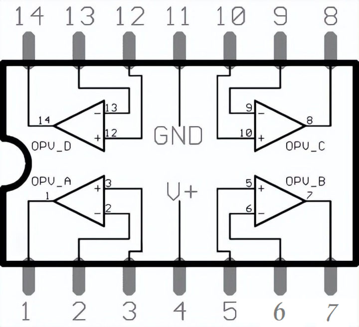
Figure1-LM324 Pinout
Ⅱ LM324 Op-Amp Pin Configuration
|
Pin Number |
Pin Name |
Description |
|
1 |
OUTPUT1 |
The output of Op-Amp 1 |
|
2 |
INPUT1- |
Inverting Input of Op-Amp 1 |
|
3 |
INPUT1+ |
Non-Inverting Input of Op-Amp 1 |
|
4 |
VCC |
Positive Supply Voltage |
|
5 |
INPUT2+ |
Non-Inverting Input of Op-Amp 2 |
|
6 |
INPUT2- |
Inverting Input of Op-Amp 2 |
|
7 |
OUTPUT2 |
The output of Op-Amp 2 |
|
8 |
OUTPUT3 |
The output of Op-Amp 3 |
|
9 |
INPUT3- |
Inverting Input of Op-Amp 3 |
|
10 |
INPUT3+ |
Non-Inverting Input of Op-Amp 3 |
|
11 |
VEE, GND |
Ground or Negative Supply Voltage |
|
12 |
INPUT4+ |
Non-Inverting Input of Op-Amp 4 |
|
13 |
INPUT4- |
Inverting Input of Op-Amp 4 |
|
14 |
OUTPUT4 |
The output of Op-Amp 4 |
Ⅲ LM324 Quad Op-Amp IC Features and Specifications
- Integrated with four Op-Amps in a single package
- Wide power supply Range
- Singe supply – 3V to 32V
- Dual supply – ±1.5V to ±16V
- Low Supply current – 700uA
- Single supply for four op-amp operations enables reliable operation
- Operating ambient temperature – 0˚C to 70˚C
- Soldering pin temperature – 260 ˚C (for 10 seconds – prescribed)
Ⅳ LM324 Working Principle
A simulation circuit is designed here to help you better understand the working principle of LM324. Below is a very simple circuit where the LED is automatically turned on or off based on the LDR value.
Its closed state is shown in the figure below:

Figure2-LM324 Working Principle
In figure2, An LDR is connected at the input and an LED is connected at its output. A variable resistor is used to control the sensitivity of the LDR sensor.
Its open state is shown in the figure below:
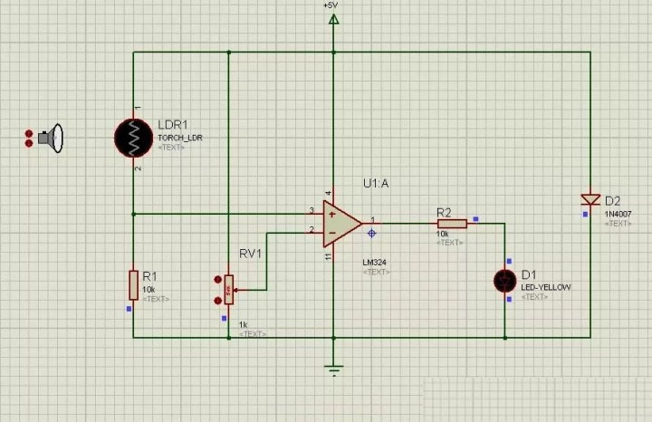
Figure3-variable resistor used
Ⅴ 4 Example Circuits of LM324 Quad Op Amp ICs
5. 1. Function generator circuit built with LM324 chip
Below is the function generator circuit to be built using the LM324 op-amp chip.
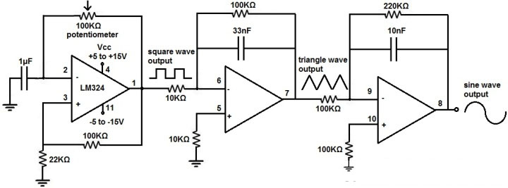
Figure4-Function generator circuit built with LM324 chip
The breadboard circuit for the above circuit is shown below:

Figure5- breadboard circuit for the above circuit
The above is the function generator chip built with LM324
Working Principle:
As mentioned above, the LM324 is powered by a DC voltage through pins 4 and 11. We feed anything from 5V to 15V to pin 4-VCC and anything from -5V to -15V to pin 11-GND, this builds up enough power for the circuit to run.
First Op-Amp: This op-amp generates a square wave. The 100KΩ potentiometer allows us to vary the frequency of the circuit. And it is a way to adjust the frequency of the output signal. So after the first op amp, we have a square wave. Next is the integrator circuit. When you feed a square wave into an integrator circuit, the output is a triangle wave.
After the second op-amp, we now have a triangle waveform as our second waveform. We then feed this triangle waveform into another integrator circuit. When you feed a triangle waveform into an integrator circuit, the output is a sine waveform.
After the third op-amp, we have a sine waveform, which is our third waveform. This circuit is very basic.
The first op-amp produces a square wave. We feed this square wave into an integrator circuit which outputs a triangle wave. We then feed this triangle wave into a second integrator circuit which outputs a sine wave.
The 100KΩ potentiometer allows a fairly wide frequency range, so the circuit provides good frequency adjustment, just like a standard function generator.
The circuit also allows easy amplitude adjustment. If you're using a DC power supply to power this circuit, all you have to do is adjust the voltage on the DC power supply to change the amplitude of the signal. If you're powering the circuit from batteries then you'll need to add the number of batteries needed to get the maximum voltage you need, then add a small value potentiometer, say 200Ω-500Ω, to allow voltage adjustment.
This is how a function generator circuit is built using an LM324 op-amp chip.
5.2. Circuit diagram of mobile phone detector based on LM324 IC
The circuit diagram of the mobile phone detector based on LM324 IC is listed below.
The design of this circuit is easy to understand, and it can detect the mobile phone within a distance of 10 to 20 meters. The detection range mainly depends on the mobile phone, because each one has its signal generation capabilities. This circuit only detects the coded signal, not the voice content. The coded signal can be received when the phone is answering a call, or it can be used while talking while sending and receiving text messages. This circuit can work for many purposes like searching a lost mobile phone or looking for a cell phone in restricted areas.

Figure6-Circuit diagram of mobile phone detector based on LM324 IC
It is simple to use basic electrical and electronic components to build circuits. The LM324 operational amplifier is the heart of the circuit. The IC contains four high-gain op amps, but this circuit uses only a single op-amp out of four.
A transistor 2N4401 is connected at the output of the LM324 to turn on the LED as well as the piezo buzzer. The number of LED connections can also be increased to 25. The circuit can operate from 4.5 V to 12 V DC. If the circuit is running below 9V (lower voltage), then we need to replace the current limiting resistor value from 470 Ω to 220 Ω for all LEDs in the circuit. Circuit sensitivity can be modified with a 100K variable resistor.
5.3. Temperature sensing and control system based on LM324 IC
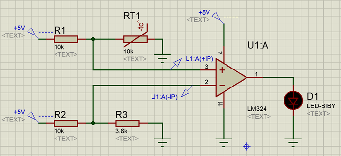
Figure7-Temperature sensing and control system based on LM324 IC
At temperature = 25˚C, RT=10kὨ. Inverted input = 1.32V, non-inverted input = 2.36V. So the output is high and it can drive the motor on via a transistor or a relay.
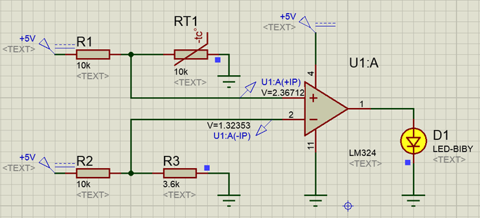
Figure8-Temperature sensing and control system based on LM324 IC 1
At Temperature = above 70˚C, RT=3kὨ. Inv Input=1.32V and Non-Inv Input=1.06V.
Thus, Output is LOW and it can drive a motor OFF through a transistor or relay.

Figure9-Temperature sensing and control system based on LM324 IC 2
If the temperature is to be monitored at three or four locations on the motor, the LM324 can be used in the following configuration. An example of the orientation of two temperature senses is RT1 and RT2.
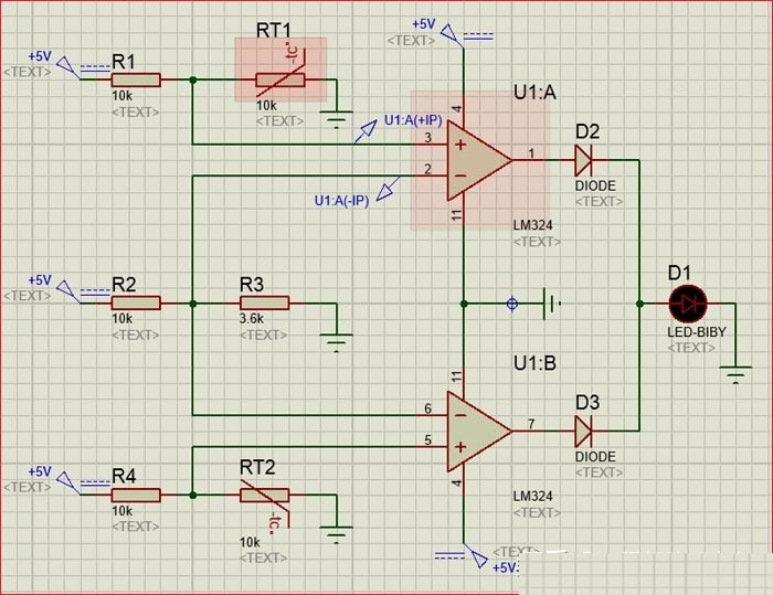
Figure10-Temperature sensing and control system based on LM324 IC 3
5.4. Dark detector example using LM324
In this dark detector example, an LM324 acts as a comparator. A photoresistor is a light sensor. LDR resistance changes according to the amount of light available in its surroundings. So, we can use this photoresistor as a light sensor to detect darkness or measure light. We can also measure light with LDR. An LM324 is used instead of a microcontroller in this example.
How dark detectors work:
- We connect the LED at the output of the op-amp pin 14 through 100Ω.
- This is an indicator LED that turns on whenever the LDR detects light.
- When there is light around the LDR, the LED remains off.
- The LM342N is used as a comparator, the inverting terminal is connected to the output of the LDR, and the non-inverting terminal is connected to the variable resistor.
- When the voltage on pin 13 is greater than the voltage on pin 12, the comparator output is a 5 V output.
- This output voltage provides the forward voltage to the LED and causes it to emit light.
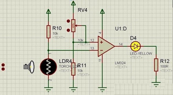
Figure11-Dark detector example using LM324
Ⅵ Replacement and Equivalent / Other Part Numbers
LM124, LM224, and LM2902 are the exact equivalents of LM324. Other possible equivalents are LF147, LF347, and LM837. Moreover, two LM358 IC can also be used as equivalents each LM358 contains two op-amps.
Ⅶ LM324 Application
- Sensor Circuits
- Small Signal Amplification
- General Operational Amplifiers Circuits
- Audio preamplifiers
- Filters
- Comparator Applications
Ⅷ How to Safely Long Run in a Circuit
It is advised against using IC above its maximum limits for long-term performance. Use no more than 32C DC when operating the IC. Always double-check the supply's polarity before applying it to the IC. Reverse polarity has the potential to harm the chip's internal circuitry. Always operate the IC at temperatures greater than 0°C and less than +70°C. Additionally, keep items in temperatures between -65 and +150 degrees Celsius.
Ⅸ LM324 PDF
LM324 Datasheet
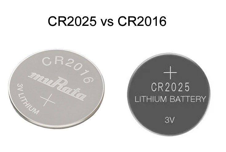 CR2025 vs CR2016: Which one you should choose ?5/8/2024 27
CR2025 is a type of lithium coin cell battery. It's a small, round, flat battery commonly used in various electronic devices such as watches, calculators, remote controls, key fobs, and small electronic gadgets. The "CR" in its name stands for lithium manganese dioxide chemistry, and "2025" refers to its dimensions: 20mm diameter and 2.5mm height. These batteries are known for their long shelf life and stable voltage output, making them popular choices for low-power devices.
Read More >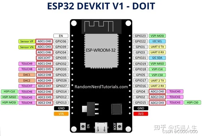 How to resolve the WiFi and ADC2 Sharing Dilemma?4/19/2024 47
ESP32-CAM can be used in various Internet of Things situations and is suitable for home smart devices, industrial wireless control, wireless Monitoring, QR wireless identification, wireless positioning system signals, and other IoT applications are ideal solutions for IoT applications.
Read More >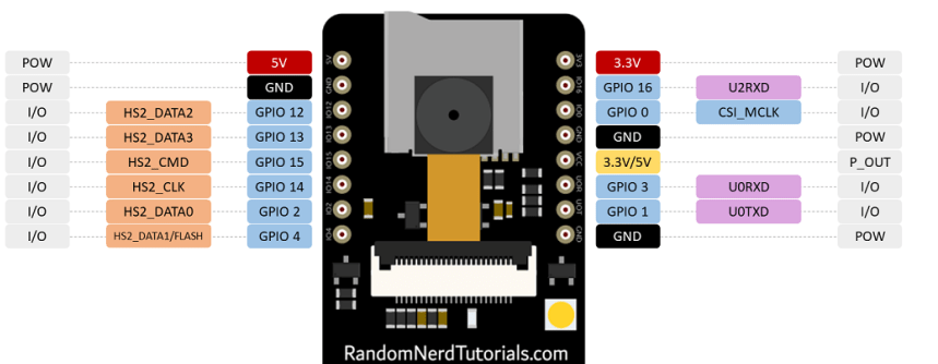 ESP32-CAM Pinout Explanation and How to Use?4/18/2024 131
ESP32-CAM is a development board with an ESP32-S chip, an OV2640 camera, a microSD card slot, and several GPIOs for connecting peripherals. ESP32-CAM is a small-sized camera module. The module can work independently as the smallest system, with a size of only 27*40.5*4.5mm.
Read More >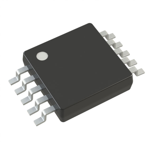 Stand-Alone Linear Li-Ion / Li-Polymer Charge Management Controller MCP738334/9/2024 70
The MCP73833/4 is a highly advanced linear charge management controller for use in space-limited, cost sensitive applications. Both a 10-lead, MSOP and a 10-lead, DFN packaging measuring 3 mm by 3 mm are offered for the MCP73833/4. In addition to its tiny size, the MCP73833/4 is perfect for portable applications because it requires a few additional components.
Read More >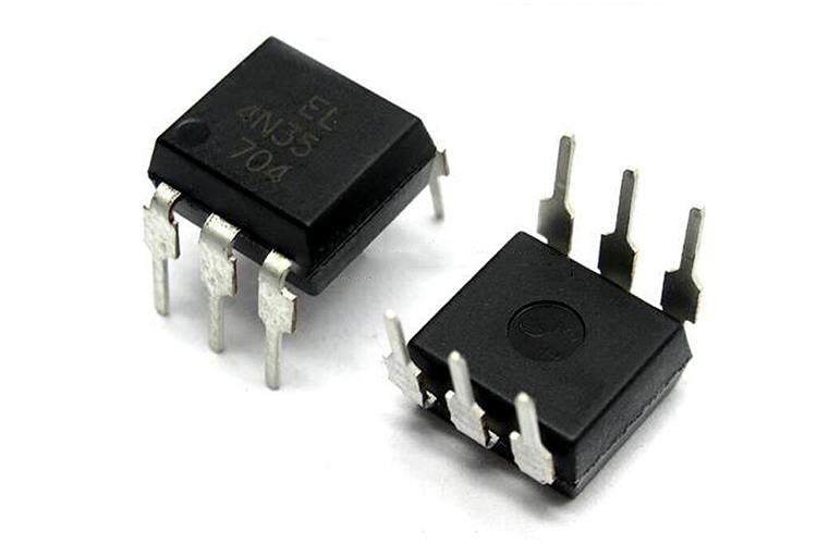 Optocoupler IC 4N35: Pinout, Datasheet, Features and Applications3/26/2024 129
In the realm of electronics, where connectivity and isolation are paramount, the 4N35 optocoupler IC stands as a beacon of reliability and versatility. This small yet mighty device plays a crucial role in ensuring signal integrity and safety across a wide range of applications. In this article, we delve into the intricacies of the 4N35 optocoupler IC, exploring its datasheet, pinout, circuit diagram, and diverse uses.
Read More >
SUPPORT
ABOUT BITFOIC
QUICK LINKS
Connect with us
Tel: 86-755-23606554
E-mail: [email protected]
Address: Room A29, 24 / F, Hoi Tak Wai, Prince Edward industrial building, 706 Prince Edward Road East, San Po Kong, Kowloon,Hongkong
Mon-Fri: 09.30 AM - 18.30 PM


