


How to create a smart Wi-Fi doorbell with an ESP32 and camera?
Project Introduction
Nowadays, security systems are one of the most researched fields. With the increase in security threats, companies are introducing new intelligent security products to counter these threats. The Internet of Things (IoT) is an additional advantage in this field; it can automatically trigger events in any emergency, such as alarms, fire brigades, or your neighbors. Today, we'll construct a smart Wi-Fi doorbell using an ESP32 and a camera.
Table of content
Components needed
ESP32-CAM
FTDI programming board
220V AC to 5V DC converter
buzzer
button
Light emitting diode (2)
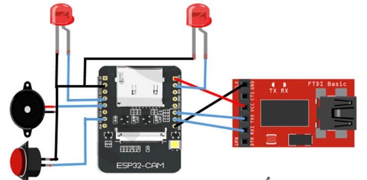
Circuit schematic
The circuit diagram of this smart Wi-Fi doorbell is as simple as connecting two LEDs, a button, and a buzzer to the ESP32 GPIO pins. The buzzer will sound whenever the button is pressed. One LED indicates power status and the other LED indicates network status. If the ESP is connected to the network, the network LED will be high, otherwise, it will flash.
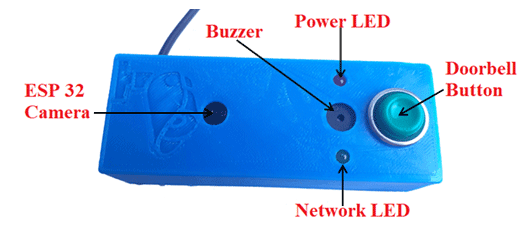
This is what the Wi-Fi video doorbell setup looks like in a 3D-printed case:
IFTTT setup for Wi-Fi doorbell
IFTTT is a free web-based service that allows users to create chains of simple conditional statements called "recipes" triggered based on changes to other web services such as Gmail, Facebook, Instagram, and Pinterest. IFTTT stands for “If This Then That.”
In this project, IFTTT is used to send an email when the temperature or humidity exceeds predefined limits. We have previously used IFTTT in many IoT-based projects to send emails or SMS for specific events like excessive power usage, high pulse rate, intruder entry, etc.
First, log into IFTTT using your credentials or sign up if you don't have an account.
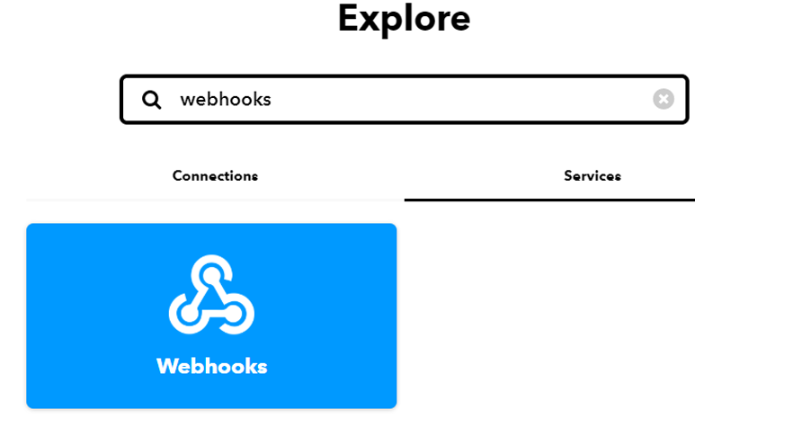
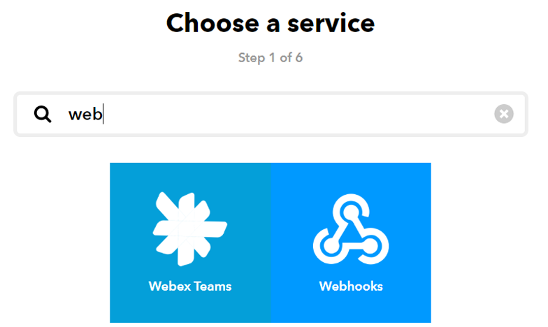
Now search for “Webhooks” and click on “Webhooks” in the Services section.
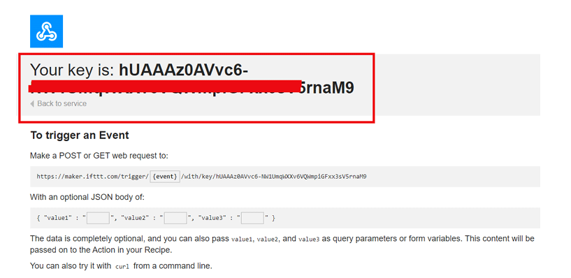
Now, click on Documents in the upper right corner of the Webhooks window to get the private key.
Copy this key. It is a part of the curriculum.
After obtaining the private key, we will create a small program using webhooks and email services. Click on your profile and then select Create to create an applet.

Now in the next window, click on the "This" icon.
Proceed to the search section, type in "Webhooks," and choose it.
Now select the "Receive Web Request" trigger and in the next window, enter the event name as button_pressed and click on Create Trigger.
Now to complete the applet, click "that" to create a reaction for the button_pressed event.

Here, the phone will play a pre-designated song when the IoT doorbell button is pressed. Search for "Android devices" in the search section.

Now on your Android device, select the "Play specific song" trigger.
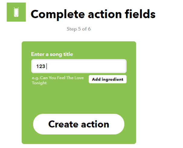
Now enter the name of the song that you want to play when the doorbell button is pressed. In my case, I was playing a song called "123" from my Google Play Music. You can also use Spotify or other music apps.
After that, click on Create Action and then click on Finish to complete the process.
Now create another applet that sends a message with a web link to your phone when the doorbell button is pressed.
So, to create this applet, select "Webhooks" in the "this" section and "Android SMS" in the "that" section.
Now it will ask for the phone number and message body. For this Wi-Fi doorbell project, we are sending a message with a link to the web server so that you can see the live video stream directly.
Code Explanation
Some of the code's most significant components are explained below.
First, include all the required library files for this code.
#include "esp_camera.h"
#include <WiFi.h>
Then enter the Wi-Fi credentials.
const char* ssid = "Wi-Fi Name";
const char* password = "Wi-Fi Password";
After that, enter the IFTTT hostname and private key that you copied from the IFTTT website.
const char *host = "maker.ifttt.com";
const char *privateKey = "Your Private Key";
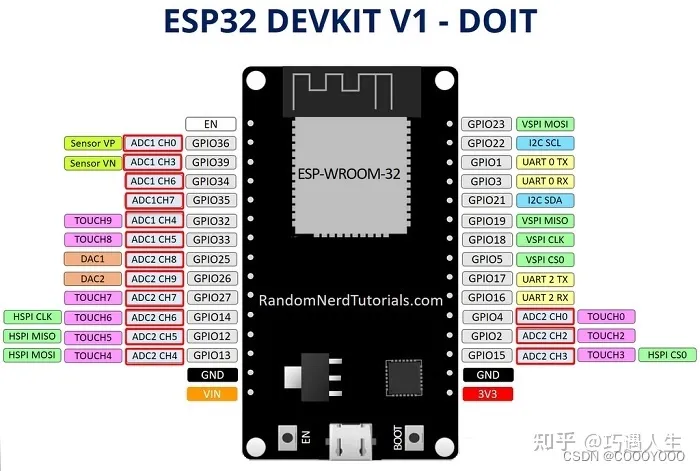
Define all the pins that you are using in this project. I'm connecting the push button, LED, and buzzer using the GPIO 2, 14, and 15 pins.
const int buttonPin = 2;
const int led1 = 14;
const int buzzer = 15;
Inside the void setup loop, define the button pin as input and the LED and buzzer pins as output.
void setup() {
pinMode(buttonPin, INPUT);
pinMode(led1, OUTPUT);
pinMode(buzzer, OUTPUT);
It will attempt to establish a Wi-Fi connection with the provided credentials, and upon successful connection, the LED status will transition from low to high.
WiFi.begin(ssid, password);
int led = LOW;
while (WiFi.status() != WL_CONNECTED) {
delay(500);
Serial.print(".");
digitalWrite(led1, led);
led = !led;
}
Serial.println("");
Serial.println("WiFi connected");
digitalWrite(led1, HIGH);
The ESP32 will restart when it is not connected to a network until it does so.
while (WiFi.status() == WL_DISCONNECTED) {
ESP.restart();
digitalWrite(led1, LOW);
Serial.print("Connection Lost");
When the ESP32 detects that a button has been pressed and is in the LOW state (pulled high), it transmits an event and activates the buzzer for three seconds.
int reading = digitalRead(buttonPin);
if (buttonState == LOW) {
send_event("button_pressed");
Serial.print("button pressed");
digitalWrite(buzzer, HIGH);
delay(3000);
digitalWrite(buzzer, LOW);
 How to resolve the WiFi and ADC2 Sharing Dilemma?4/19/2024 24
ESP32-CAM can be used in various Internet of Things situations and is suitable for home smart devices, industrial wireless control, wireless Monitoring, QR wireless identification, wireless positioning system signals, and other IoT applications are ideal solutions for IoT applications.
Read More >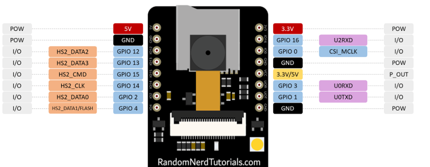 ESP32-CAM Pinout Explanation and How to Use?4/18/2024 56
ESP32-CAM is a development board with an ESP32-S chip, an OV2640 camera, a microSD card slot, and several GPIOs for connecting peripherals. ESP32-CAM is a small-sized camera module. The module can work independently as the smallest system, with a size of only 27*40.5*4.5mm.
Read More >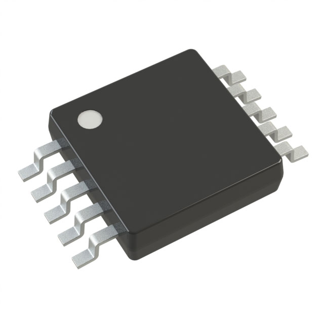 Stand-Alone Linear Li-Ion / Li-Polymer Charge Management Controller MCP738334/9/2024 62
The MCP73833/4 is a highly advanced linear charge management controller for use in space-limited, cost sensitive applications. Both a 10-lead, MSOP and a 10-lead, DFN packaging measuring 3 mm by 3 mm are offered for the MCP73833/4. In addition to its tiny size, the MCP73833/4 is perfect for portable applications because it requires a few additional components.
Read More >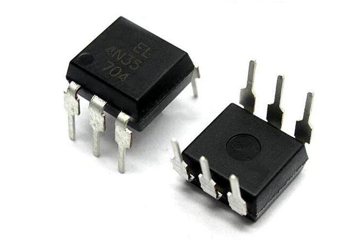 Optocoupler IC 4N35: Pinout, Datasheet, Features and Applications3/26/2024 103
In the realm of electronics, where connectivity and isolation are paramount, the 4N35 optocoupler IC stands as a beacon of reliability and versatility. This small yet mighty device plays a crucial role in ensuring signal integrity and safety across a wide range of applications. In this article, we delve into the intricacies of the 4N35 optocoupler IC, exploring its datasheet, pinout, circuit diagram, and diverse uses.
Read More > UA741CP datasheet ,Specification, Features and Application3/21/2024 101
The UA741CP is a general-purpose operational amplifier in an 8-pin DIP package. The high common-mode input voltage range and lack of latch-up make the amplifier ideal for voltage follower applications.
Read More >
SUPPORT
ABOUT BITFOIC
QUICK LINKS
Connect with us
Tel: 86-755-23606554
E-mail: contact@bitfoic.com
Address: Room A29, 24 / F, Hoi Tak Wai, Prince Edward industrial building, 706 Prince Edward Road East, San Po Kong, Kowloon,Hongkong
Mon-Fri: 09.30 AM - 18.30 PM


