


ATmega328P Microcontroller: How to Program ATmega328P with Bootloader on Arduino Uno?
Introduction
We know that the chip commonly used in the Arduino development board is the AVR microcontroller series produced by Atmel. The most common is the ATmega328P, widely used on the Arduino Uno development board. Other commonly used AVR chips include the ATmega2560 and ATmega32U4. It is very convenient to use the Arduino platform to develop AVR microcontrollers. The Arduino IDE provides a clean, easy-to-use development environment that simplifies writing and uploading code. It provides a set of simplified function libraries and API so that developers can easily interact with the hardware of ATmega328P without a deep understanding of the underlying register operations.
Catalog
Ⅰ What is ATmega328 ?
The Atmega328P is an 8-bit microcontroller chip that can be used in various control systems due to its strong performance and low power consumption. Because it can be found in Arduino boards, it is the most widely used AVR controller. The ATmega328P is capable of supporting analog input/output pins and serial communication interfaces. It employs 2KB of SRAM memory and 32KB of programmable flash memory. The Atmega328P is a popular microcontroller with many uses, particularly in embedded systems, automation, and electrical equipment control.
Ⅱ ATMega328 Pinout
ATMega328 Pinout 28 PDIP
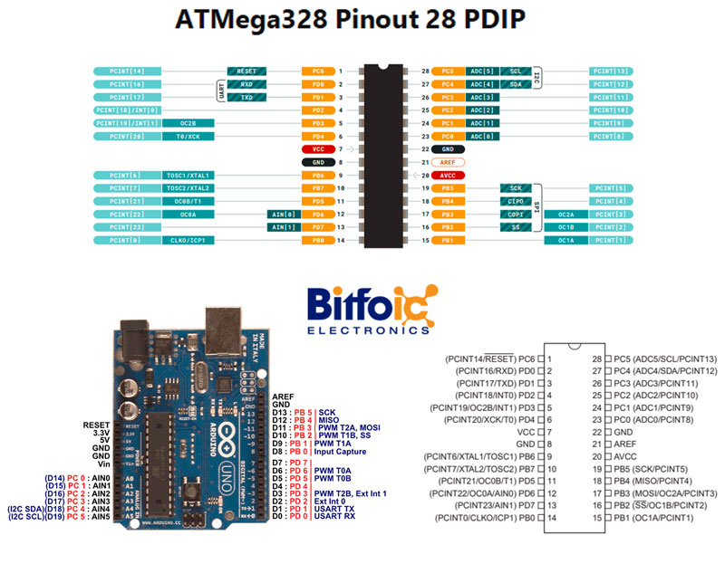
Figure1-ATMega328 Pinout 28 PDIP
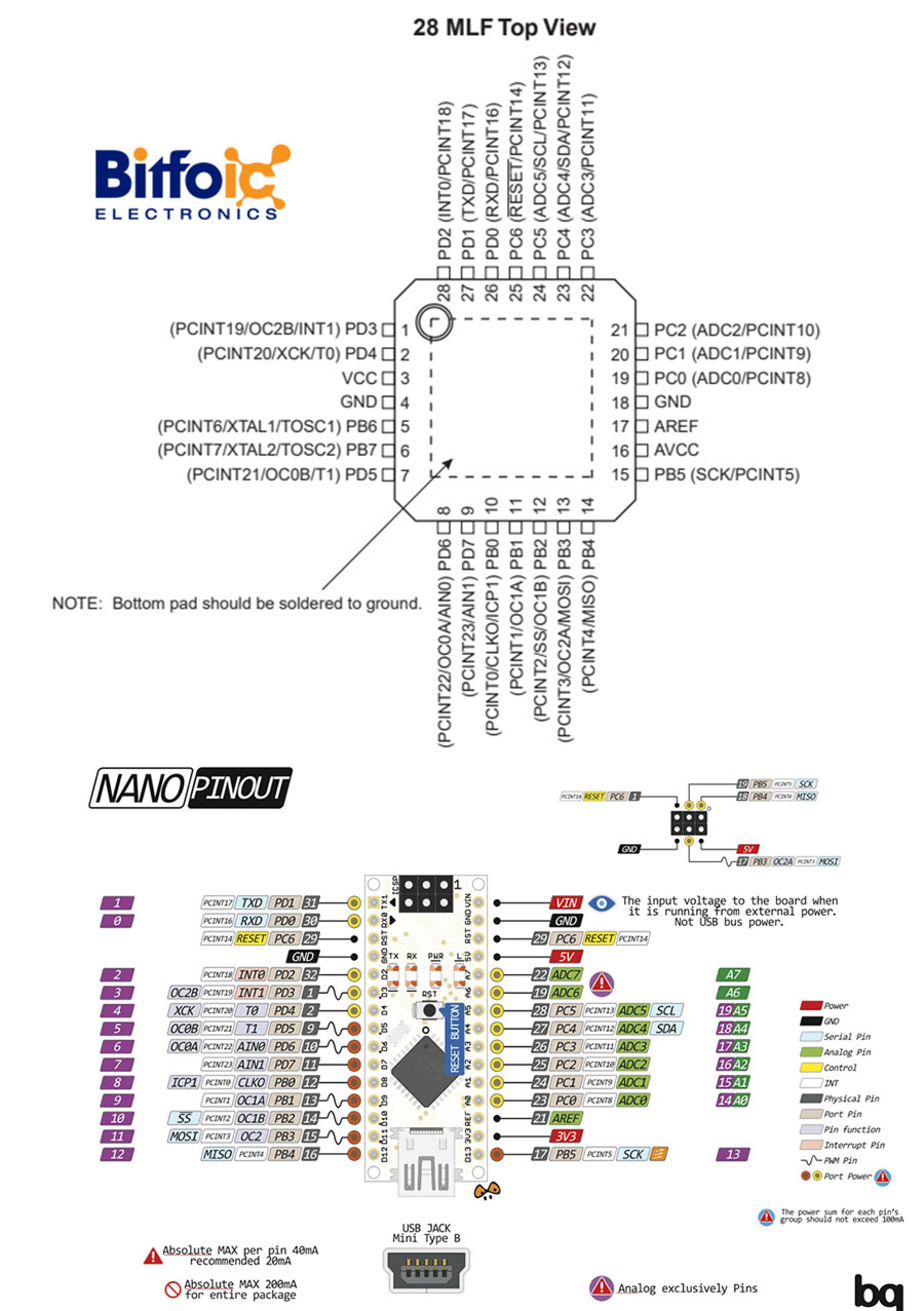
Figure2-28MLF Top View
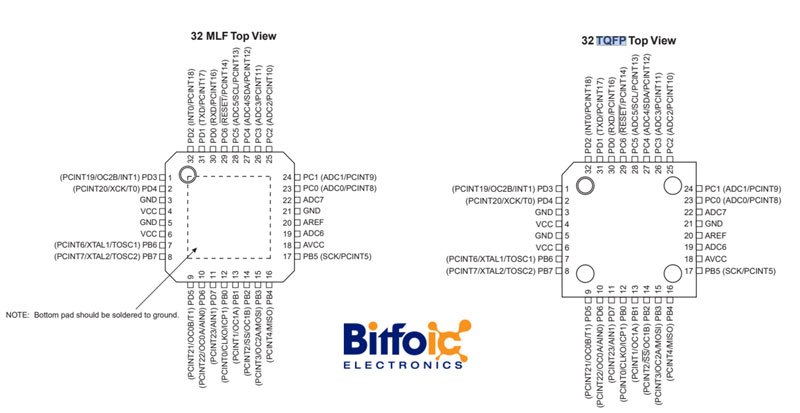
Figure3- 32MLF and 32TQFP
Ⅲ ATMega328 Pinout Configuration
|
Pin No. |
Pin name |
Description |
Secondary Function |
|
1 |
PC6 (RESET) |
Pin6 of PORTC |
Pin by default is used as RESET pin. Only when the RSTDISBL Fuse has been programmed may PC6 be used as an I/O pin. |
|
2 |
PD0 (RXD) |
Pin0 of PORTD |
RXD (Data Input Pin for USART) USART Serial Communication Interface [Can be used for programming] |
|
3 |
PD1 (TXD) |
Pin1 of PORTD |
TXD (Data Output Pin for USART) USART Serial Communication Interface [Can be used for programming] INT2( External Interrupt 2 Input) |
|
4 |
PD2 (INT0) |
Pin2 of PORTD |
External Interrupt source 0 |
|
5 |
PD3 (INT1/OC2B) |
Pin3 of PORTD |
External Interrupt source1 OC2B is a PWM timer/counter that compares the match B output. |
|
6 |
PD4 (XCK/T0) |
Pin4 of PORTD |
T0( Timer0 External Counter Input) XCK ( USART External Clock I/O) |
|
7 |
VCC |
Connected to a positive voltage |
|
|
8 |
GND |
|
Connected to ground |
|
9 |
PB6 (XTAL1/TOSC1) |
Pin6 of PORTB |
XTAL1 refers to the external clock input or chip clock oscillator pin 1. TOSC1 (Timer Oscillator pin 1) |
|
10 |
PB7 (XTAL2/TOSC2) |
Pin7 of PORTB |
XTAL2 (Chip Clock Oscillator pin 2) TOSC2 (Timer Oscillator pin 2) |
|
11 |
PD5 (T1/OC0B) |
Pin5 of PORTD |
T1(Timer1 External Counter Input) OC0B(PWM - Timer/Counter0 Output Compare Match B Output) |
|
12 |
PD6 (AIN0/OC0A) |
Pin6 of PORTD |
AIN0(Analog Comparator Positive I/P) OC0A, which is a PWM timer/counter output that compares match A output. |
|
13 |
PD7 (AIN1) |
Pin7 of PORTD |
AIN1(Analog Comparator Negative I/P) |
|
14 |
PB0 (ICP1/CLKO) |
Pin0 of PORTB |
ICP1(Timer/Counter1 Input Capture Pin) The PB0 pin may be used to output the divided system clock. |
|
15 |
PB1 (OC1A) |
Pin1 of PORTB |
OC1A (Timer/Counter1 Output Compare Match A Output) |
|
16 |
PB2 (SS/OC1B) |
Pin2 of PORTB |
SS (SPI Slave Select Input). When the controller functions as a slave, this pin is low. [Serial Peripheral Interface (SPI) for programming] OC1B (Timer/Counter1 Output Compare Match B Output) |
|
17 |
PB3 (MOSI/OC2A) |
Pin3 of PORTB |
MOSI (Master Output Slave Input). This pin receives the data when the controller functions as a slave. [Serial Peripheral Interface (SPI) for programming] OC2 (Timer/Counter2 Output Compare Match Output) |
|
18 |
PB4 (MISO) |
Pin4 of PORTB |
MISO (Master Input Slave Output). When the controller acts as a slave, the data is sent to the master by this controller through this pin. [Serial Peripheral Interface (SPI) for programming] |
|
19 |
PB5 (SCK) |
Pin5 of PORTB |
SCK (SPI Bus Serial Clock). For precise data transfer, this controller and another system use this clock. [Serial Peripheral Interface (SPI) for programming] |
|
20 |
AVCC |
|
Power for Internal ADC Converter |
|
21 |
AREF |
Analog Reference Pin for ADC |
|
|
22 |
GND |
|
GROUND |
|
23 |
PC0 (ADC0) |
Pin0 of PORTC |
ADC0 (ADC Input Channel 0) |
|
24 |
PC1 (ADC1) |
Pin1 of PORTC |
ADC1 (ADC Input Channel 1) |
|
25 |
PC2 (ADC2) |
Pin2 of PORTC |
ADC2 (ADC Input Channel 2) |
|
26 |
PC3 (ADC3) |
Pin3 of PORTC |
ADC3 (ADC Input Channel 3) |
|
27 |
PC4 (ADC4/SDA) |
Pin4 of PORTC |
ADC4 (ADC Input Channel 4) SDA (Two-wire Serial Bus Data Input/output Line) |
|
28 |
PC5 (ADC5/SCL) |
Pin5 of PORTC |
ADC5 (ADC Input Channel 5) SCL (Two-wire Serial Bus Clock Line) |
Ⅳ ATmega328 Features
- CPU: The ATmega328 features a high-performance 8-bit AVR RISC-based CPU with a clock speed of up to 20 MHz. It executes most instructions in a single clock cycle, providing efficient and fast processing.
- Memory: It has 32KB of in-system programmable Flash memory for storing the program code, 2KB of SRAM for data storage, and 1KB of EEPROM for non-volatile data storage.
- I/O Pins: The microcontroller has a total of 23 general-purpose I/O (GPIO) pins, including 14 digital input/output pins and 6 analog input pins. These pins can be configured for various purposes, such as reading sensors, driving output devices, and communication.
- Communication Interfaces: ATmega328 supports multiple communication interfaces, including UART (Universal Asynchronous Receiver-Transmitter), SPI (Serial Peripheral Interface), and I2C (Inter-Integrated Circuit). These interfaces allow the microcontroller to communicate with other devices such as sensors, displays, and other microcontrollers.
- Timers and PWM: It has three timers/counters and six PWM (Pulse Width Modulation) channels, which can be used for generating accurate time delays, measuring external events, and controlling the intensity of analog output signals.
- Power Management: The ATmega328 offers various power-saving modes to optimize power consumption, making it suitable for battery-operated applications.
- Development Tools: Several development tools and software are available for programming and debugging ATmega328, including the Arduino IDE, which provides an easy-to-use platform for beginners.
Ⅴ How to Use ATMega328P using Arduino
Since ATmega328P is used in Arduino Uno and Arduino nano boards, you can directly replace the Arduino board with an ATmega328 chip. For that first, you need to install the Arduino bootloader into the chip (Or you can also buy a chip with a bootloader – ATMega328P-PU). This IC with a bootloader can be placed on an Arduino Uno board and burn the program. Once the Arduino program is burnt into the IC, it can be removed and used in place of the Arduino board, along with a Crystal oscillator and other components as required for the project. Below is the pin mapping between Arduino Uno and the ATmega328P chip.
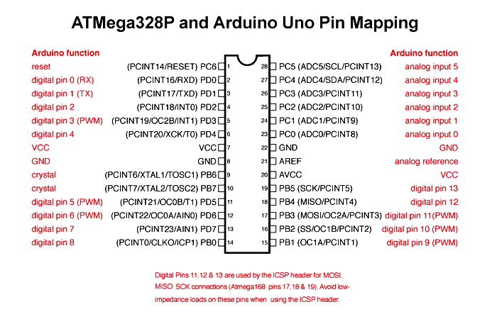
Figure4-pin mapping
Ⅵ How to Program ATmega328P with Bootloader on Arduino Uno?
Materials Needed
- Arduino Uno
- ATmega328P
Introduction
If you buy a brand new ATmega328P, and you want to program it, a natural way to do it is to unplug the chip that was plugged into the board, and plug in the new chip so that it can be programmed.

Figure5- ATmega328P
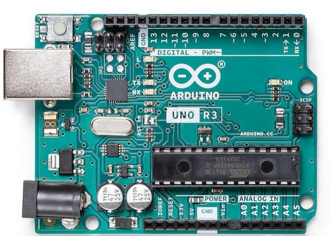
Figure6-Arduino Uno
Regretfully, this plan fails because the ATmega328P chip is programmed by the Arduino Uno via the onboard serial port; however, the new ATmega328P lacks the internal Bootloader functionality that is required to program the ATmega328P chip via the serial port.
Therefore, it is necessary to program the Bootloader into the ATmega328P first.
Step1: Program the Bootloader
The Arduino Uno can function as a programmer (ISP) and can be used to program the new ATmega328P's bootloader.
The Arduino Uno can be made into a programmer by downloading the "ArduinoISP" code included with the Arduino IDE to it:
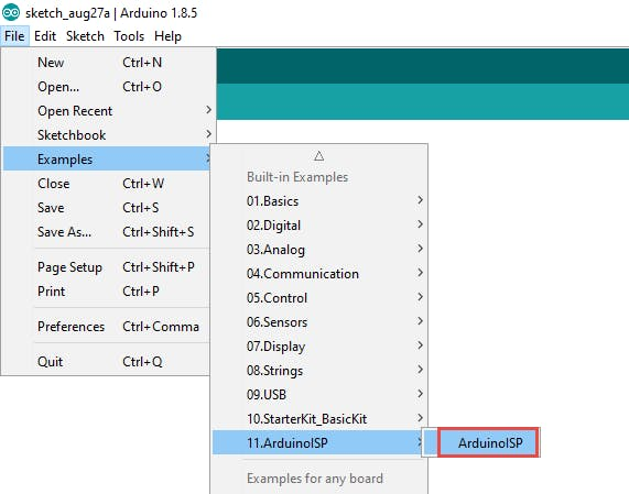
Figuure7-Choose ArduinoISP
Step2: Program the Arduino Uno with the programmer
Before programming starts, connect the hardware as shown in the figure below:
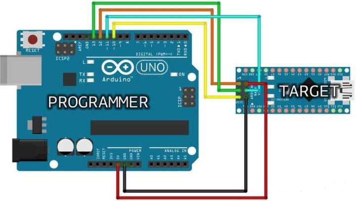
Figure8-Hardware connection
Step3:Hardware connection when programming Bootloader
Keep in mind that pin 10 of the programmer's Arduino Uno is linked to the target board's RESET pin.
Select Arduino as a programmer in Arduino IDE:
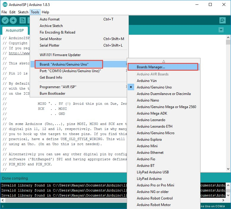
Figure9-Arduino IDE
Step4: The programmer selects Arduino as ISP
Select "Arduino Uno" for the development board in the Arduino IDE. Click "Burn Bootloader" in the menu:

Figure10-Arduino Uno
Once the fire has begun to burn, the prompt reads:
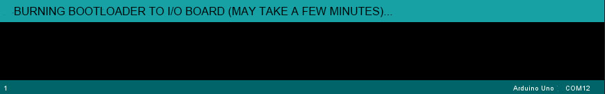
Figure11-burning bootloader
Following a successful burning, the following prompt appears:
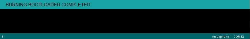
Figure12-prompt
Step5: Download Program
After programming the Bootloader, you can program the ATmega328P that has been programmed with the Bootloader through the serial port that comes with the Arduino Uno board. Before programming, you need to remove the ATmega328p on the Arduino Uno board as a programmer. It is the same as inserting the ATmega328P into the Arduino Uno development board to program it. The hardware connection is as follows:

Figure13- Bootloader
Step6: Hardware connection when programming the Flash program
In the Arduino IDE, write a program to blink an LED and choose "ArduinoISP" as the programmer:
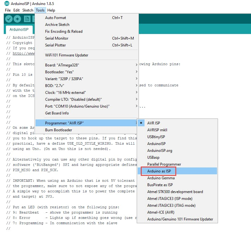
Figure14-ArduinoISP
Step7: Select Programmer ArduinoISP
Then, you can download the program normally.
Ⅶ Applications
There are hundreds of applications for ATMEGA328P:
- utilized in boards such as the Arduino Micro, Nano, and UNO.
- Industrial control systems.
- SMPS and Power Regulation Systems.
- Digital data processing.
- Analog signal measuring and manipulations.
- vending machines and coffee makers
- Motor control systems.
- Display units.
- Peripheral Interface system.
Ⅷ ATmega328P Datasheet
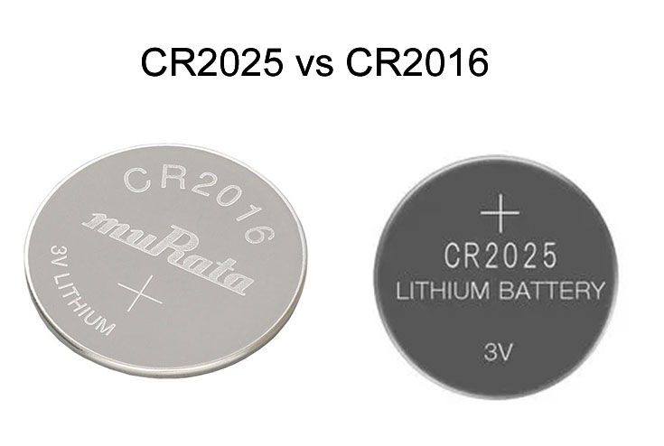 CR2025 vs CR2016: Which one you should choose ?5/8/2024 28
CR2025 is a type of lithium coin cell battery. It's a small, round, flat battery commonly used in various electronic devices such as watches, calculators, remote controls, key fobs, and small electronic gadgets. The "CR" in its name stands for lithium manganese dioxide chemistry, and "2025" refers to its dimensions: 20mm diameter and 2.5mm height. These batteries are known for their long shelf life and stable voltage output, making them popular choices for low-power devices.
Read More >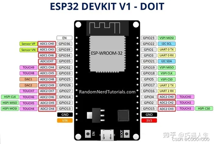 How to resolve the WiFi and ADC2 Sharing Dilemma?4/19/2024 47
ESP32-CAM can be used in various Internet of Things situations and is suitable for home smart devices, industrial wireless control, wireless Monitoring, QR wireless identification, wireless positioning system signals, and other IoT applications are ideal solutions for IoT applications.
Read More >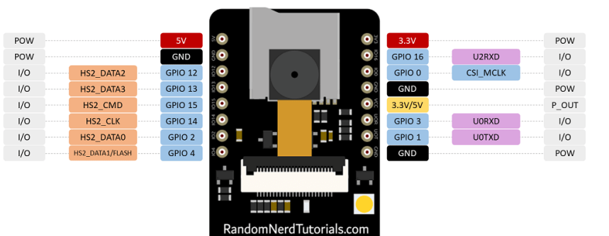 ESP32-CAM Pinout Explanation and How to Use?4/18/2024 132
ESP32-CAM is a development board with an ESP32-S chip, an OV2640 camera, a microSD card slot, and several GPIOs for connecting peripherals. ESP32-CAM is a small-sized camera module. The module can work independently as the smallest system, with a size of only 27*40.5*4.5mm.
Read More >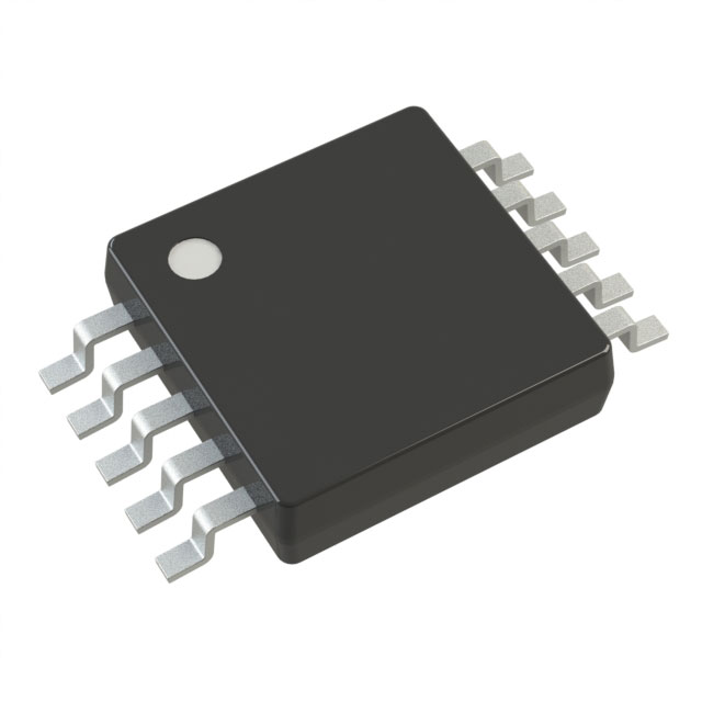 Stand-Alone Linear Li-Ion / Li-Polymer Charge Management Controller MCP738334/9/2024 71
The MCP73833/4 is a highly advanced linear charge management controller for use in space-limited, cost sensitive applications. Both a 10-lead, MSOP and a 10-lead, DFN packaging measuring 3 mm by 3 mm are offered for the MCP73833/4. In addition to its tiny size, the MCP73833/4 is perfect for portable applications because it requires a few additional components.
Read More >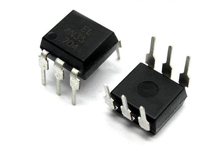 Optocoupler IC 4N35: Pinout, Datasheet, Features and Applications3/26/2024 130
In the realm of electronics, where connectivity and isolation are paramount, the 4N35 optocoupler IC stands as a beacon of reliability and versatility. This small yet mighty device plays a crucial role in ensuring signal integrity and safety across a wide range of applications. In this article, we delve into the intricacies of the 4N35 optocoupler IC, exploring its datasheet, pinout, circuit diagram, and diverse uses.
Read More >
SUPPORT
ABOUT BITFOIC
QUICK LINKS
Connect with us
Tel: 86-755-23606554
E-mail: [email protected]
Address: Room A29, 24 / F, Hoi Tak Wai, Prince Edward industrial building, 706 Prince Edward Road East, San Po Kong, Kowloon,Hongkong
Mon-Fri: 09.30 AM - 18.30 PM


