


A Comprehensive Guide to ATMega328P Pinout
Introduction
ATMega328P is a commonly used microcontroller, and its pinout refers to the pin layout and function description of the microcontroller. The importance of the ATMega328P pinout is that it specifies the specific positions and functions of the input and output interfaces, power supply, and ground pins of the microcontroller, and is an important basis for circuit design and programming.
Table of Content
ATMega328P Pinout Frame Diagram
The features of ATMega328P Pinout include moderate pin count, rich functions, and flexible use. ATMega328P Pinout is divided into many types, including digital pins, analog pins, power pins, and special function pins.
The ATmega328P chip has 28 pins, and the usage and pin diagram configuration details of each pin are shown in the figure below:
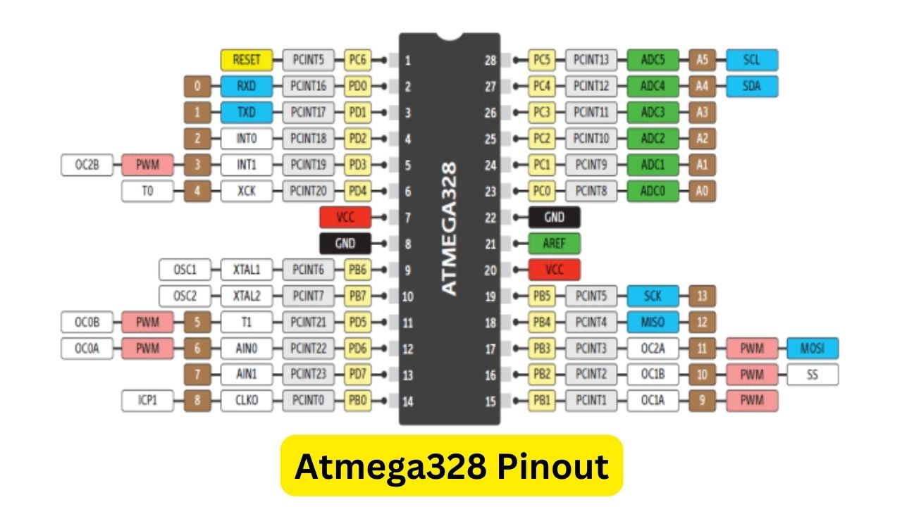
ATMega328P Pinout
I/O Pins
This microcontroller has three digital ports (B, C, D), namely PORTB, PORTC and PORTD. All these pins can be used as digital input/output. Best of all, every port can be used for other purposes. To use them as output/input or any other function, they should be defined first, otherwise, all I/O pins will not have any default function. The controller’s digital I/O pins are:
PBO -GPIO14
PB1 -GPIO15
PB2 - GPIO16
PB3- GPIO17
PB4 - GPIO18
PB5 - GPIO19
PB6- GPIO9
PB7 - GPIO10.
PC0 - GPIO23
PC1 - GPIO24
PC2 -GPIO25
PC3 - GPIO26
PC4 - GPIO27
PC5 - GPIO28
PC6 -GPIO1
PD0 - GPIO2
PD1 - GPIO3
PD2- GPIO4
PD3 - GPIO5
PD4 - GPIO6
PD5 - GPIO11
PD6 -GPIO12
PD7 -GPI013
Interrupt pin
Most electrical functions require an interruption to the system to operate, such as AC dimmers, etc. ATmega328P provides support for 2 interrupt pins within the controller, which can be used to draw the attention of the CPU at any time. The interrupt pins of ATmega328P are as follows:
- INo -GPIO4
- IN1 -GPIO5
UART communication module
While there are multiple communication systems within this device and modules, the most common is USART. It is one of the simplest and easiest methods for most developers and systems to implement and understand. In this method, two wires are used to send and receive data. The USART pins of ATmega328P are:
- RX -GPIO2
- TX -GPIO3
Data can be sent at a specified send rate within the controller, but an external clock pin can also be used to keep the data synchronized:
- XCK -GPIO6
The USART/UART communication system can be used to program microcontrollers.
SPI communication
It is one of the best serial communication systems for multiple peripheral situations. The SPI protocol allows multiple devices to communicate using the same channel. It consists of four wires, two for data sending, and one for clock, but the fourth wire is used to select the peripheral called select slave. When more peripherals are selected as slaves, the number of pins will increase. The SPI pins of the microcontroller are:
- MOSI - GPIO17
- MISO - GPIO18
- SS - GPIO16
- SCK -GPIO19
I2C communication module
Most peripherals come with IPC communication, which is a time-specific method. The I-C protocol uses only one data line and one clock line. The data lines will transmit and receive data, and the clock lines will send clock pulses to keep the data in sync. The I2C pins on the microcontroller are:
- SDA -GPIO27
- SCL -GPIO28
Timer module
The ATtiny328P has two internal timers that can be used to make counters and generate pulses. Both timers rely on oscillators. Both timers can operate using internal and external clocks, but they also have an internal pin that can count based on external pulses. All these pins in microcontroller ATmega328P are as follows:
- T0 -GPIO6
- T1 -GPIO11
- TOSC1 -GPIO9
- TOSC2-GPIO10
- ICP1 -GPIO
Among them, ICP1 is the input capture pin, which can capture external pulses at specific time intervals. An input pulse on this pin generates a timestamp that can tell when an external signal is received.
System clock
The internal clock and external clock pulses can be divided by prescalers and their values can be received at external pins. The external pins for the divided clock pulse are:
- CLKo - GPIO14
Comparator module
The microcontroller has an internal comparator module for analog signals. This module takes inputs in inverting and non-inverting forms and can be further used for any internal purpose and can also be used to generate output signals. The comparator pins of the microcontroller are as follows:
- ANO (positive)-GPIO12
- AN1(negative)-GPIO13
Capture/Compare/PWM Channel
ATmega328P has six capture/compare/PWM pins for generating the required time pulse-based signal, it uses a prescaler to divide the time pulse, all these pins are:
OCOB -GPIO11
OCOA -GPIO12
OC1A - GPIO15
OC1B - GPIO16
OC2A -GPIO17
OC2B -GPIO5
ADC channel
ATmega328P has 6 ADC channels that can convert analog signals into digital signals. The analog converter needs to be activated first via its power pin (AVCC). The ADC channel uses the supply voltage as a reference to differentiate between different levels of the analog signal. The analog pins of the controller are:
ADCO - GPIO23
ADC1 -GPIO24
ADC2 - GPIO25
ADC3 - GPIO26
ADC4 -GPIO27
ADC5 -GPIO28
AVCC-Pin 20
AREF pin
Sometimes the analog signal voltage fluctuates, but the controller is constantly measuring based on the controller's power input. The analog voltage reference AREF will be used to measure it through any other power input or the power supply of an analog signal-generating device. This pin will detect the maximum value of the analog signal and then be able to give the correct output. The AREF pin in ATmega328P is:
- AREF -GPIO21
RESET
In ATmega328, some resets can restart the microcontroller in certain situations. Among all these resets, there is an external reset that can use an external signal to reset the device:
- RESET -GPIO1
Power
Every controller requires power to operate, and there is always a power input pin. The number of power pins of ATmega328P is three. One pin is for voltage and the remaining two are for common ground. Both ground pins are connected internally and it doesn't matter which one is used. The power pins of the microcontroller are:
- l VCC-pin 7
- l GND - Pin 8, Pin 22
Oscillator
The controller is equipped with an 8MHz variable oscillator. However, it can also use an external oscillator up to 40MHz. To use an external oscillator, an oscillator pin is required for input and output signals. These pins are as follows:
- XTAL1 -GPIO9
- XTAL2- GPIO10
Specific applications of ATMega328P Pinout
In circuit design, it is necessary to select appropriate pins for configuration and use according to specific needs. In programming, you need to understand the specific functions of each pin and the corresponding input and output signals to correctly control and use these pins. Like Arduino, the pins become specific to their function. When using the ATmega328P's compiler, almost all pins can be used as GPIO. However, when using Arduino, each pin will only perform a specific function, but the controller can still perform all operations like the ATmega328P.
Conclusion
ATMega328P Pinout is a crucial foundation for circuit design and programming. It is necessary to understand and master its characteristics, classification, and specific application methods. In practical applications, it is essentical to use the ATMega328P Pinout flexibly and conduct circuit design and programming according to the actual situation to achieve more efficient and stable project development.
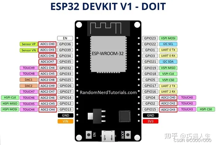 How to resolve the WiFi and ADC2 Sharing Dilemma?4/19/2024 23
ESP32-CAM can be used in various Internet of Things situations and is suitable for home smart devices, industrial wireless control, wireless Monitoring, QR wireless identification, wireless positioning system signals, and other IoT applications are ideal solutions for IoT applications.
Read More >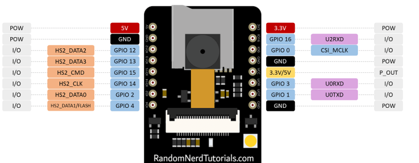 ESP32-CAM Pinout Explanation and How to Use?4/18/2024 51
ESP32-CAM is a development board with an ESP32-S chip, an OV2640 camera, a microSD card slot, and several GPIOs for connecting peripherals. ESP32-CAM is a small-sized camera module. The module can work independently as the smallest system, with a size of only 27*40.5*4.5mm.
Read More >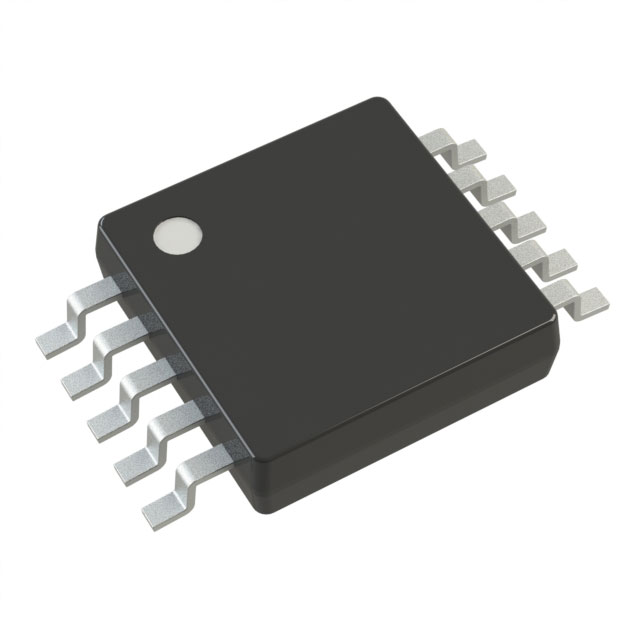 Stand-Alone Linear Li-Ion / Li-Polymer Charge Management Controller MCP738334/9/2024 61
The MCP73833/4 is a highly advanced linear charge management controller for use in space-limited, cost sensitive applications. Both a 10-lead, MSOP and a 10-lead, DFN packaging measuring 3 mm by 3 mm are offered for the MCP73833/4. In addition to its tiny size, the MCP73833/4 is perfect for portable applications because it requires a few additional components.
Read More >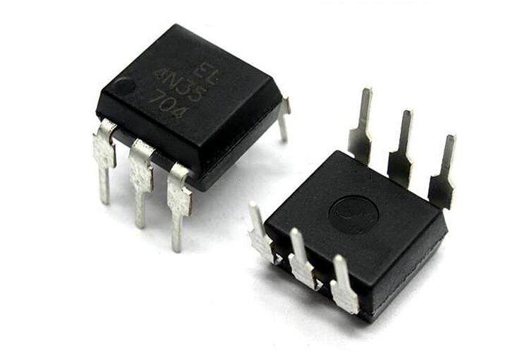 Optocoupler IC 4N35: Pinout, Datasheet, Features and Applications3/26/2024 98
In the realm of electronics, where connectivity and isolation are paramount, the 4N35 optocoupler IC stands as a beacon of reliability and versatility. This small yet mighty device plays a crucial role in ensuring signal integrity and safety across a wide range of applications. In this article, we delve into the intricacies of the 4N35 optocoupler IC, exploring its datasheet, pinout, circuit diagram, and diverse uses.
Read More >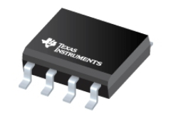 UA741CP datasheet ,Specification, Features and Application3/21/2024 100
The UA741CP is a general-purpose operational amplifier in an 8-pin DIP package. The high common-mode input voltage range and lack of latch-up make the amplifier ideal for voltage follower applications.
Read More >
SUPPORT
ABOUT BITFOIC
QUICK LINKS
Connect with us
Tel: 86-755-23606554
E-mail: contact@bitfoic.com
Address: Room A29, 24 / F, Hoi Tak Wai, Prince Edward industrial building, 706 Prince Edward Road East, San Po Kong, Kowloon,Hongkong
Mon-Fri: 09.30 AM - 18.30 PM


