


Development Board ESP32: ESP32 Wi-Fi, Bluetooth module and How to set it up?
Introduction
ESP32, like Arduino, is a development board. That means it has all the features you need to create your projects. In this article, you will learn about the ESP32 Wi-Fi and Bluetooth module and how to set it up. Besides, you can know about what it is and how it works and what are its special features.
Catalog
Ⅰ What is ESP32?
The ESP8266 Wi-Fi module is one of the most popular and useful modules of the past few years. Various versions of such modules are available on the market.
The ESP32 module is an upgraded version of the ESP8266. In addition to the Wi-Fi module, this module also contains a Bluetooth 4.0 module. With a dual-core CPU operating at 80 to 240 MHz, containing two Wi-Fi and Bluetooth modules and various input and output pins, the ESP32 is ideal for IoT projects.
The small ESP32 package has a high level of integrations such as:
- Antenna switches
- Balun to control RF
- Power amplifier
- Low noise reception amplifier
- Filters and power management modules
On top of all that, it achieves very low power consumption through power-saving features including clock synchronization and multiple modes of operation. The ESP32 chip’s quiescent current is less than 5 μA which makes it the ideal tool for your battery-powered projects or IoT applications.
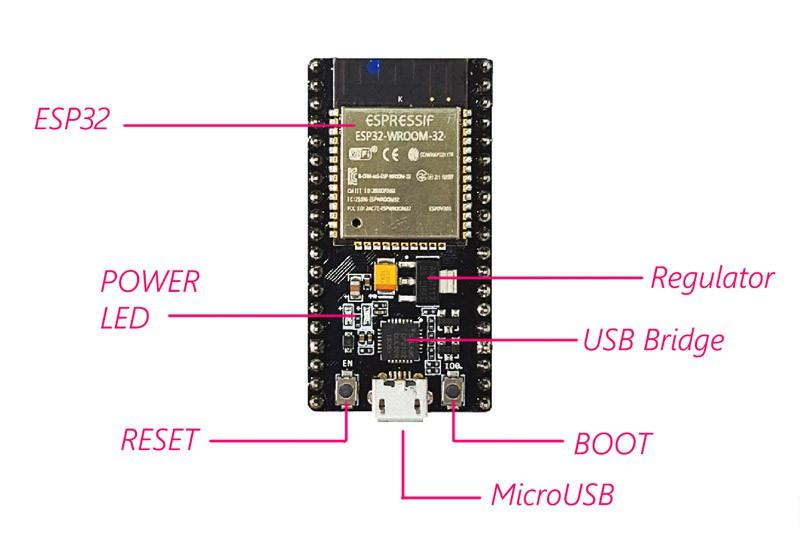
Figure1-ESP32
Ⅱ ESP32 Architectural Block Diagram
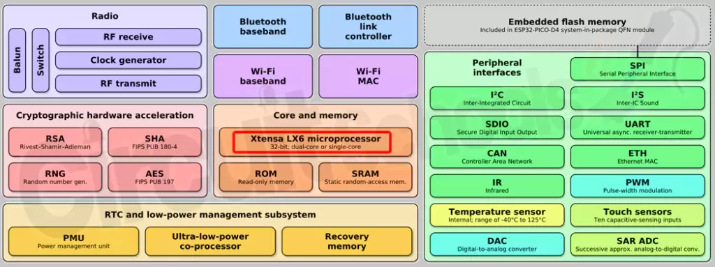
Figure2-ESP32 Architectural Block diagram
Ⅲ ESP32 Pinout
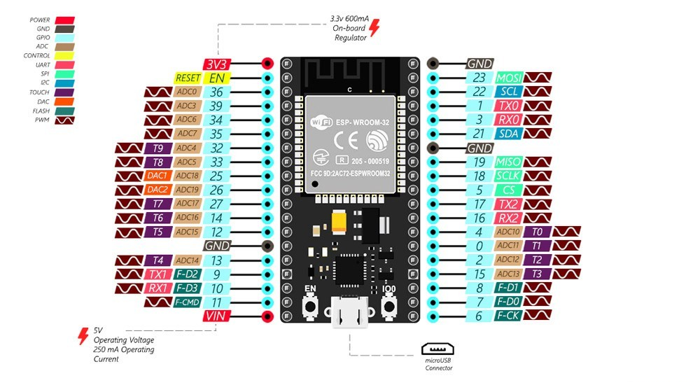
Figure3-ESP32 pinout
Although the ESP32 has fewer pin counts than commonly used processors, you won't have any problems multiplexing multiple functions on the pins.
WARNING: The voltage level on the ESP32 pins is 3.3 volts. If you want to interface the ESP32 to other devices that operate on 5 volts, you should use a level shifter to convert the voltage levels.
- Power Pins: The module has two power pins - 5V and 3.3V. You can use these two pins to power other devices and modules.
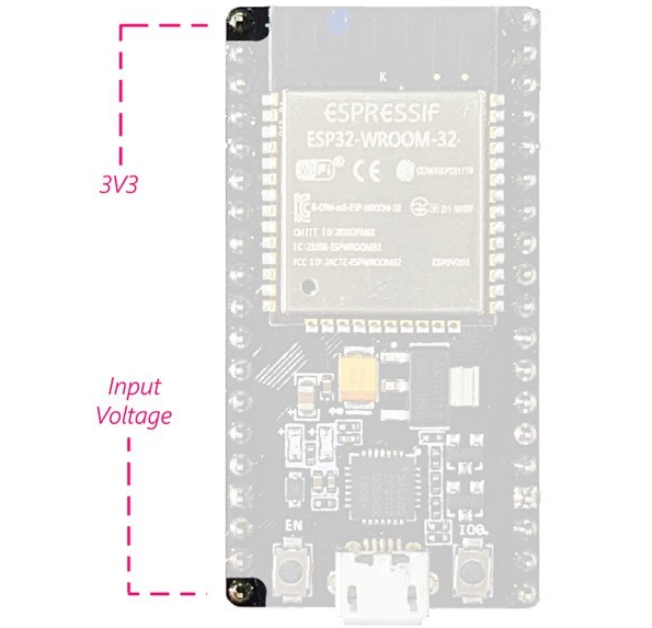
Figure4-Power Pins
- GND pin: There are 3 pins for the ground of this module.
- Enable Pin (EN): This pin is used to enable and disable the module. A high level on the pin allows for the module and a low level disables the module.
- Input/Output Pins (GPIO): You can use 32 GPIO pins to communicate with LEDs, switches, and other I/O devices.
You can pull up or pull down these pins internally. Note: GPIO6 to GPIO11 pins (SCK/CLK, SDO/SD0, SDI/SD1, SHD/SD2, SWP/SD3, and SCS/CMD pins) are used for SPI communication of the internal flash memory of the module, and we do not recommend using them.
- ADC: You can use the 16 ADC pins on this module to convert an analog voltage (the output of some sensors) to a digital voltage. Some of these converters are connected to internal amplifiers and are capable of measuring small voltages with high accuracy.
- DAC: The ESP32 module has two digital-to-analog converters with 8-bit precision.
- Touchpads: There are 10 pins on the ESP32 module, which are sensitive to capacitance changes. You can connect these pins to some pads (pads on the PCB) and use them as touch switches.
- SPI: There are two SPI interfaces on this module, which can be used to connect the display screen, SD/microSD memory card module, external flash memory, etc.
- I2C: SDA and SCL pins are used for I2C communication.
- Serial communication (UART): There are two UART serial interfaces on the module. Using these pins, you can transfer up to 5Mbps between two devices. UART0 also has CTS and RTS controls.
- PWM: Almost all ESP32 input/output pins can be used for PWM (Pulse Width Modulation). Use these pins to control motors, LED lights, colors, etc.
Ⅳ ESP32 Module Mode
ESP32 module mode ESP32 chip has 5 modes:
- Active Mode: In this mode, all parts of the Wi-Fi and Bluetooth transmitter and receiver are active. In this case, the current draw is between 80 and 260 mA.
- Modem Sleep Mode: The processor is still active, but Wi-Fi and Bluetooth are disabled. In this case, the current consumption is between 3 and 20mA.
- Light sleep mode: The central processor stops working, but the RTC unit and ULP processor unit are still active. The current consumption is about 0.8 mA.
- Deep sleep mode: only the RTC unit is active. In this case, the data for Wi-Fi and Bluetooth communication is stored in the memory of the RTC. In this mode, the current consumption is between 10 and 150µA.
- Sleep Mode: All units are disabled except the RTC timer used for the clock and some I/O pins connected to RTC. An RTC timer or a connected pin can wake up the chip from this state. In this case, the current consumption is about 2.5µA. See the module datasheet for more information.
Ⅴ ESP32 PDF
ESP32 Technical Reference Manual
Ⅵ ESP32 VS. ESP8266
There are various types of ESP32 and ESP8266 modules available in the market. In this section, ESP8266 NodeMcu and ESP32 DEV modules are compared: ESP8266 NodeMcu ESP32 DEV Module Power Supply 3.3V 3.3VCPU Tensilica L106 32-bit Xtensa Dual Core 32-bit LX6 Bluetooth None Complies with Bluetooth v4.2 BR/EDR and BLE Specifications GPIO1732 Flash Size Max 16MB Max 16MADC 10bit 12bit DAC No 2*8bitUART22 Usually, ESP32 modules are more expensive than ESP8266. So if you don't need Bluetooth, digitizers, lots of I/O pins, and... you can save money by buying an ESP8266 module.
Required Materials
- ESP32 module
- Arduino IDE
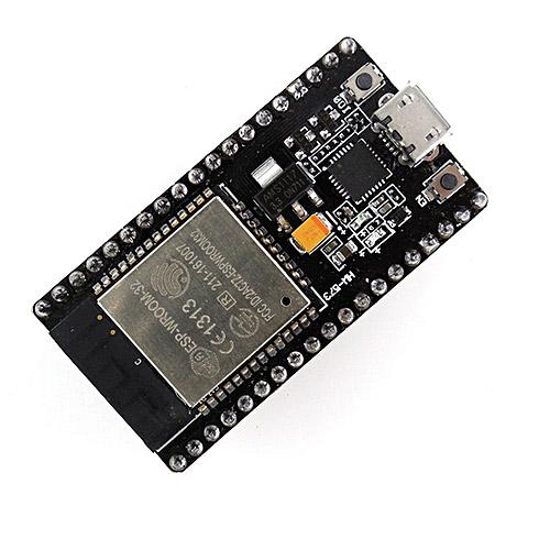
Figure5-ESP32 module
Ⅶ How to Install ESP32 on Arduino IDE?
The installation process for the ESP32 is almost the same as for the ESP8266. To install ESP32 on Arduino IDE, follow these steps:
NOTE: You need Arduino IDE 1.8.5 or higher to install the ESP32 on it.
Step 1: Download the required files from GitHub
Download the ESP32 Arduino Core from your GitHub account.
Step 2: Move the file to the Arduino sketchbook location
By default, the Arduino sketchbook is located in "My Documents". To find the exact path to the schematic, check the preferences from the File menu.
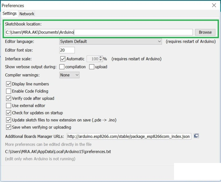
Figure6-Move the file to the Arduino sketchbook location
Create a new folder called hardware next to the Arduino folder in the sketchbook location.
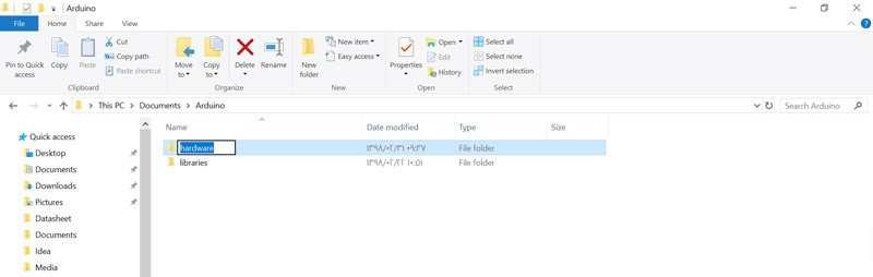
Figure7-new folder
Inside the hardware folder create a folder called espressif, then inside the espressif folder create another folder called esp32. In the end, the path you created should look like the image below:
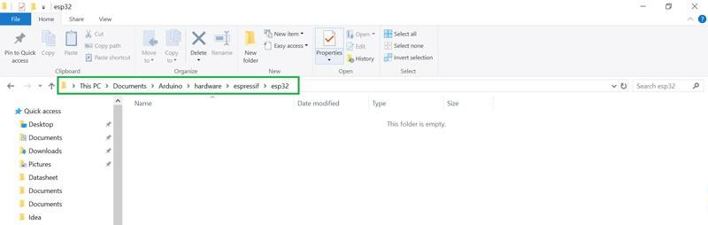
Figure8-espressif
Unzip the file you downloaded in the previous step and move it to this address.
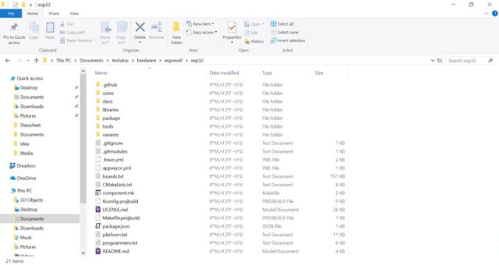
Figure9-Unzip the file
Step 3: Run get.exe
To install the ESP32 on the Arduino software, you need to have the Xtensa GNU compiler collection installed on your system. Go to esp32>tools and run the get.exe file.
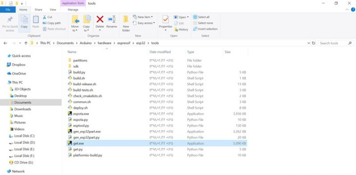
Figure10-Run get.exe
After running get.exe, the required files will be automatically downloaded and transferred to the tools folder. This step may take some time.
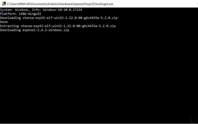
Figure11-tools folder
After the installation is complete, new files must be added to the tools folder.
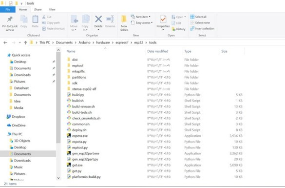
Figure12-new files
Uploading code on ESP32 using the Arduino IDE Uploading code on the ESP32 module is similar to other Arduino development boards. You can use the Arduino built-in examples such as Blink to test it. Note: If you have not installed the CP2102 driver on your computer before, you should download it from here, and then install it. To upload code, select the board type from the Tools menu. Then select the serial port connected to the board and click upload.
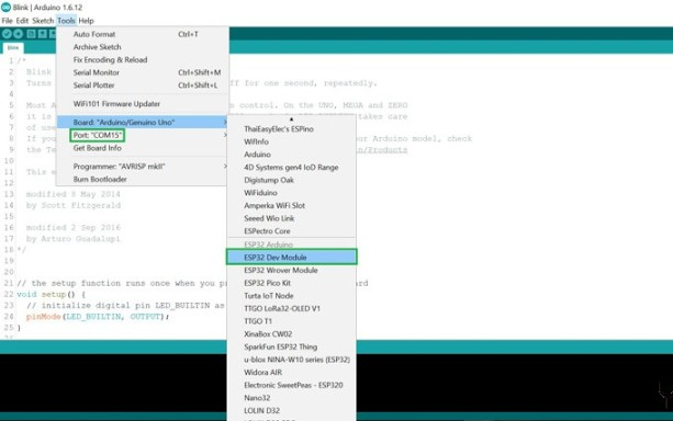
Figure13-Uploading code

Figure14-Uploading code
Troubleshooting
Don't worry if you encounter the following errors. This problem usually occurs when programming the ESP32. Perform the following steps to resolve the issue:
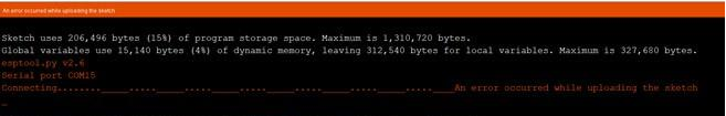
Figure15-Troubleshooting
- Make sure the upload baud rate is set correctly. Typically, this baud rate should be 115200.
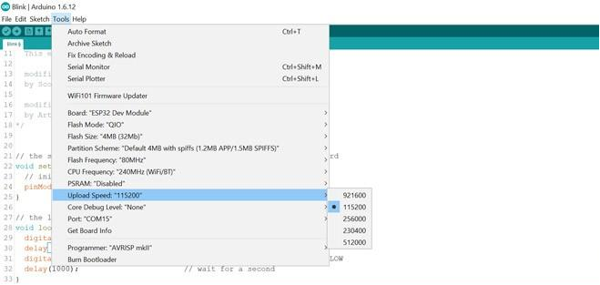
Figure16-baud rate
- Press and hold the Boot button on the development board.
- Click the Upload option.
- When you see the message "Writing at 0x00001000 … (100%)", take your finger off the "Boot" button.
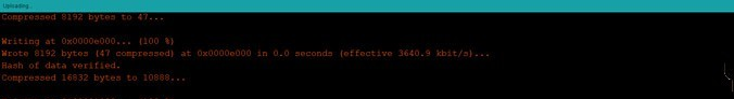
Figure17-Boot
Ⅸ How to select an ESP32 development board?
Before selecting an ESP32 development board, you need to take into account certain aspects:
- Pin numbers and configuration: it is important to have access to the board’s pinout in order to make correct use of it.
- Serial -USB interface and voltage regulator: These two features are found in practically all development boards. These are the ones that allow the board to be connected directly to the computer to be energized and programmed.
- Battery connector: if you are thinking of venturing into low-consumption systems with batteries, you can opt for boards that already include battery connectors.
- Extra functions: many development boards for ESP32 come with extra features such as cameras, OLED displays, LoRa modules, etc.
Ⅷ Other ESP32 Development Boards and Specialty Projects
There are other development boards with particular characteristics that can be useful in more specific projects:
- ESP32-CAM: it is a development board based on ESP32 that has a camera, microSD card slot, and several GPIOs.
- TTGO T-Call ESP32 with SIM800L GSM / GPRS: development board that combines an ESP32 module with one SIM800L GSM / GPRS.
- M5Stack: it is a very economical development board that has a 2-inch color LCD display, a nice housing, a USB type C connector for programming and power, I2C connectivity, and a group of GIPOs pins to connect it to all kinds of devices. .
- ESP-EYE: is a development board for image recognition and audio processing, which can be used in various IoT applications. It has an ESP32 chip, a 2-megapixel camera, and a microphone. ESP-EYE offers a lot of storage, with 8 Mbyte of SRAM and 4 Mbyte of flash memory. It also supports image transmission over Wi-Fi and debugging through a Micro-USB port.
 DC-DC converter RFB-0505S: Specification,Datasheet,Features and Applications6/13/2024 447
The RFB-0505S is a DC-DC converter from RECOM Power, Inc., belonging to the RFB Series. It features a Single In-Line Package (SIP7) and provides a single unregulated output. This converter offers 1 watt of power with an output voltage of 5V and is rated for an isolation voltage of 1kV.
Read More > Understanding the RFMM-0505S DC-DC Converter: A Comprehensive Guide6/4/2024 626
In the world of electronics, ensuring efficient power management is crucial for the performance and reliability of devices. One of the key components in achieving this is the DC-DC converter. Today, we dive into the specifics of the RFMM-0505S DC-DC converter, exploring its features, applications, and benefits.
Read More > 12V DC-DC Converter AM2G-0512SZ: Specifications, Datasheet, Applications and Features6/3/2024 537
A DC-DC converter is an essential electronic device to convert a direct current (DC) source from one voltage level to another. These converters are widely employed in various applications, including portable electronic devices, automotive systems, and renewable energy installations.
Read More > What is LM3900 Quadruple Norton Operational Amplifier?5/30/2024 1127
The LM3900 consists of four independent dual-input internally compensated amplifiers. These amplifiers are specifically designed to operate on a single power supply voltage and provide a large output voltage swing. They utilize current mirrors to achieve in-phase input functionality. Applications include AC amplifiers, RC active filters, low-frequency triangle waves, square wave, and pulse waveform generation circuits, tachometers, and low-speed, high-voltage digital logic gates.
Read More > Exploring the MMBT3906 Transistor: A Comprehensive Guide5/24/2024 776
The goal of the Taiwan Semiconductor MMBT3906 PNP Bipolar Transistor is to provide a high surge current capability with minimal power loss. This transistor is perfect for automated installation and has high efficiency.
Read More >
SUPPORT
ABOUT BITFOIC
QUICK LINKS
Connect with us
Tel: 86-755-23606554
E-mail: [email protected]
Address: Room A29, 24 / F, Hoi Tak Wai, Prince Edward industrial building, 706 Prince Edward Road East, San Po Kong, Kowloon,Hongkong
Mon-Fri: 09.30 AM - 18.30 PM


