


What is S8050 silicon transistor ? Pinout, CAD model,Features and Circuits [with examples]
An NPN Epitaxial Si transistor-like S8050 is mainly used for switching and amplification purposes. So it is one of the most frequently used transistors in different circuit designs. This transistor has a remarkable maximum gain capacity of 400 however average gain is approximately 110 so it is applicable in amplifiers. As the name suggests, this transistor includes three layers where the P-doped layer is encapsulated in between the two N-doped layers. Here, the base terminal is a P-doped layer whereas the other two terminals like emitter and collector are N-doped, respectively. This article discusses an overview of an S8050 Transistor.
Top useful electric project using s8050. how to make a rain alarm. how to make rain detectors.
Catalog
Ⅰ What is an S8050 Transistor?
The S8050 is an NPN epitaxial silicon transistor with low voltage and high current capability, which is a highlight for push-pull amplification and general switching applications. The S8050 transistor consists of three layers, one P-doped semiconductor layer encapsulated between two other N-doped layers. The P-doped layer represents the base terminal, while the other two layers represent the emitter and collector respectively. The S8050 transistor has two PN junctions: a forward-biased emitter-base junction and a reverse-biased collector-base junction. It should be noted that the S8050 transistor must be operated in forward bias mode to obtain better performance. If the transistor is not forward-biased, there will be no collector current no matter how much voltage is applied to the base terminal. Amplification is a simple way when a voltage is applied at the base terminal, the transistor sinks a small current which is then used to control a large current at the other terminals.
ⅡS8050 Pinout
The S8050 triode mainly includes three terminals, namely the emitter, base, and collector, which are used for external connection with electronic circuits, and the three terminals are different in doping concentration. The emitter is highly doped, the base is lightly doped, and the collector is moderately doped. The former controls the number of electrons, and the latter collects the number of electrons from the base. A small current at one terminal is used to control a large current at the other terminals. The figure below shows the pinout of the S8050 transistor.
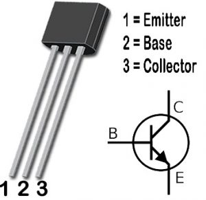
Figure1-S8050 pinout
Ⅲ Pin Configuration
|
Pin Number |
Pin Name |
Description |
|
1 |
Emitter |
Current Drains out through the emitter |
|
2 |
Base |
Controls the biasing of transistor |
|
3 |
Collector |
Current flows in through the collector |
Ⅳ S8050 CAD Model
S8050 symbol

Figure2-S8050 symbol
S8050 footprint

Figure3-S8050 footprint
S8050 3D model

Figure4-S8050 3D model
Ⅴ Features and Specifications
- Low Voltage, High Current NPN Transistor
- Small Signal Transistor
- Maximum Power: 2 Watts
- Maximum DC Current Gain (hFE) is 400
- The continuous Collector current (IC) is 700mA
- Base- Emitter Voltage (VBE) is 5V
- Collector-Emitter Voltage (VCE) is 20V
- Collector-Base Voltage (VCB) is 30V
- High Used in push-pull configuration doe Class B amplifiers
- Available in To-92 Package
Note: Complete Technical Details can be found in the S8050 datasheet given at the end of this page.
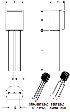
Figure5-package
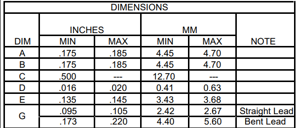
Figure6-package dimensions
Ⅵ Where to use S8050 Transistor?
The applications of the S8050 Transistor include the following.
- The general-purpose transistor-like S8050 is an ideal transistor, used to achieve general tasks within different electronic circuits. This transistor can be used as a switch within circuits that activates loads below 700mA.
- Here, 700mA of current is sufficient to manage different kinds of loads like LEDs, relays, bulbs, etc. This transistor is also used as an amplifier within small amplification phases otherwise like a separate amplifier.
- Class B Amplifiers
- Low signal applications
- Push-pull circuits
- Switch for loads in the circuit
- From low gain to high gain amplification
- Audio Amplification Circuits
- Use in circuits wherever high gain is necessary
Ⅶ S8050 Working Principle
In the S8050 NPN transistor, both the terminals emitter and collector are reverse-biased. When the base is connected to the ground, they are turned off (forward-biased) when a signal is supplied to the base pin.
The maximum gain value of the S8050 triode is 300, this value will determine the amplification capability, if the amplification ratio is high, it will be used for amplification.
However, the gain value of the collector current will be 110 and the maximum current supply across the collector terminal is 700mA, so we cannot pass more than 700mA through this transistor to control different loads. Once the current supply is applied to the base pin which must be limited to 5mA, the transistor can be biased.
Once this transistor is fully biased, it allows up to 700mA of current to be delivered through the emitter and collector terminals, hence this phase is called the saturation region. Typical voltages used on VCE or VCB are 20V and 30V respectively.
Once the current source is removed at the base terminal of the transistor, it will be turned off, hence this phase is called a cutoff region.

Figure7-working principle
In the S8050 NPN transistor, electrons are the main charge carriers, unlike PNP transistors where holes are the main charge carriers
The base is more positive concerning the emitter, the voltage on the collector must also be more positive than the base.
Two current gain factors: common emitter current gain and common base current gain play a crucial role in determining the characteristics of the transistor.
The common emitter current gain is the ratio between the collector current and the base current, this is called beta, expressed in beta, usually between 20 and 1000, but 200 is taken as a standard value.
Similarly, the common base current gain is the ratio between the collector current and the emitter current, it is called alpha, denoted by α, its value is mainly between 0.95 and 0.99, but most of the time its value is taken as 1.
Ⅷ What Parts can the S8050 be Replaced with?
- S8050 replacement
2N3904、2N3906、S9014、SS8050、2N2369、BC547
- S8050 equivalent model
2N5830、S9013
Ⅸ S8050 Application Circuits
1. The S8050 triode constitutes a push-pull amplifier (Class B amplifier) (for reference only, any mistakes are welcome to point out)
A push-pull amplifier is a multi-stage amplifier that is often used for audio amplification in speakers. The design of this circuit is very simple and requires two equal and complementary transistors to work.
Complementary means we need an NPN transistor and its equivalent PNP transistor. An NPN transistor like here would be the S8050 and its equivalent PNP transistor would be the S8550. A simple circuit diagram of a Class B amplifier using the S8050 is shown below.
Figure8- S8050 triode constitutes a push-pull amplifier
2. The S8050 triode is used as a switch (for reference only, any mistakes are welcome to point out)
When the S8050 transistor is used as a switch, it works in the saturation region and cut-off region.
When we supply current to the base of a transistor, it opens a path for the collector current to flow from the base to the emitter. During forward bias, the transistor will act as an open switch and during reverse bias, it will act as a closed switch.
The S8050 triode as a switch circuit diagram is as follows:
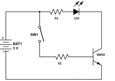
Figure9-S8050 triode is used as a switch
3. S8050 triode as an amplifier (for reference only, any mistakes are welcome to point out)
When in the active region, the S8050 transistor works as an amplifier. S8050 triode can amplify power, voltage, and current.
The most popular and most commonly used configuration is the common emitter type, where the input is always applied across the forward-biased junction of the amplifying transistor circuit, and similarly, the output can be collected through the reverse-biased junction of the transistor.
The circuit diagram of the S8050 triode as an amplifier is shown below:

Figure10-S8050 triode as an amplifier
Ⅹ2N2222 VS BC547 VS S8050
As you know 2N2222, S8050, and BC547 are NPN type and available in the TO-92 package and are quite popular, reliable, and low cost and can easily be found in any electronic components store. But what is the difference between them? Can they replace each other?
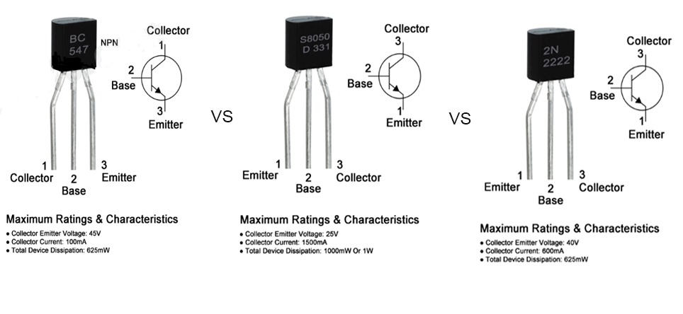
Figure11-2N2222 VS BC547 VS S8050
S8050 VS 2N2222 Pin Difference
|
Ratings & Characteristics |
2N2222 |
S8050 |
BC547 |
|
Collector-Emitter Voltage (Vceo) |
40V |
25V |
45v |
|
Collector Current (Ic) |
600mA |
1500mA |
100mA |
|
Total Device Dissipation (PD) |
625mW |
1000mW |
625Mw |
|
DC Current Gain (hFE) |
30 To 300 |
85 To 300 |
110 To 800 |
|
Frequency (fT) |
300 MHz |
100 MHz |
300 MHz |
Can We Use S8050 Instead of 2N2222?
According to the pin difference, we understood that both S8050 and 2N2222 transistors have different collector-to-emitter and collector current ratings which we can look at mainly when the transistor is used as a switch. But if you are replacing them in an amplifier circuit then you can use them interchangeably without any problem and they are pin-to-pin replacements of each other because the pin configuration of both is the same.
Can We Use BC547 Instead of S8050?
As we can see in the ratings and characteristics chart, their pin configuration is different. Therefore, if you are using it in an amplifier circuit then there will be not much difference and you can use them interchangeably but if you want to use it as a switch then first you have to check the load voltage or how much voltage the load requires. If that voltage is under 20V (S8050 collector to emitter voltage is 25V but we cannot use a transistor to its absolute maximum ratings because this makes stress on the transistor) then you can easily replace it and more of the circuit in which these transistors are used are usually 12V or under 12V. But if BC547 is driving a load higher than 25V then you cannot replace it with S8050. Moreover, the transition frequency of BC547 is 300MHz which is higher than the transition frequency of 100MHz due to which you cannot replace them in RF circuits that work above 100MHz.
Ⅺ S8050 PDF
 DC-DC converter RFB-0505S: Specification,Datasheet,Features and Applications6/13/2024 447
The RFB-0505S is a DC-DC converter from RECOM Power, Inc., belonging to the RFB Series. It features a Single In-Line Package (SIP7) and provides a single unregulated output. This converter offers 1 watt of power with an output voltage of 5V and is rated for an isolation voltage of 1kV.
Read More > Understanding the RFMM-0505S DC-DC Converter: A Comprehensive Guide6/4/2024 628
In the world of electronics, ensuring efficient power management is crucial for the performance and reliability of devices. One of the key components in achieving this is the DC-DC converter. Today, we dive into the specifics of the RFMM-0505S DC-DC converter, exploring its features, applications, and benefits.
Read More > 12V DC-DC Converter AM2G-0512SZ: Specifications, Datasheet, Applications and Features6/3/2024 538
A DC-DC converter is an essential electronic device to convert a direct current (DC) source from one voltage level to another. These converters are widely employed in various applications, including portable electronic devices, automotive systems, and renewable energy installations.
Read More > What is LM3900 Quadruple Norton Operational Amplifier?5/30/2024 1129
The LM3900 consists of four independent dual-input internally compensated amplifiers. These amplifiers are specifically designed to operate on a single power supply voltage and provide a large output voltage swing. They utilize current mirrors to achieve in-phase input functionality. Applications include AC amplifiers, RC active filters, low-frequency triangle waves, square wave, and pulse waveform generation circuits, tachometers, and low-speed, high-voltage digital logic gates.
Read More > Exploring the MMBT3906 Transistor: A Comprehensive Guide5/24/2024 779
The goal of the Taiwan Semiconductor MMBT3906 PNP Bipolar Transistor is to provide a high surge current capability with minimal power loss. This transistor is perfect for automated installation and has high efficiency.
Read More >
SUPPORT
ABOUT BITFOIC
QUICK LINKS
Connect with us
Tel: 86-755-23606554
E-mail: [email protected]
Address: Room A29, 24 / F, Hoi Tak Wai, Prince Edward industrial building, 706 Prince Edward Road East, San Po Kong, Kowloon,Hongkong
Mon-Fri: 09.30 AM - 18.30 PM


