


What is Performance Line Microcontroller Stm32f103c8 ?
The STM32F103C8 performance line microcontroller incorporates the high-performance ARM Cortex™-M3 32-bit RISC core operating at a 72 MHz frequency. This blog will introduce pinout, features, cad models, and other information about STM32F103C8. Hope it can help you.
Catalog
Ⅰ Stm32f103c8 Overview
The STM32F103C8 performance line microcontroller incorporates the high-performance ARM Cortex™-M3 32-bit RISC core operating at a 72 MHz frequency, high-speed embedded memories (Flash memory of 64 Kbytes and SRAM up to 20 Kbytes), and an extensive range of enhanced I/Os and peripherals connected to two APB buses. The STM32F103C8 offers two 12-bit ADCs, three general-purpose 16-bit timers plus one PWM timer, as well as standard and advanced communication interfaces: up to two I2Cs and SPIs, three USARTs, a USB, and a CAN.
The STM32F103C8 medium-density performance line microcontroller operates from a 2.0 to 3.6 V power supply. It is available in both the –40 to +85 °C temperature range and the –40 to +105 °C extended temperature range. A comprehensive set of power-saving modes allows the design of low-power applications.
The STM32F103xx medium-density performance line family includes devices in six different package types: from 36 pins to 100 pins. Depending on the device chosen, different sets of peripherals are included, the description below gives an overview of the complete range of peripherals proposed in this family.
These features make the STM32F103xx medium-density performance line microcontroller family suitable for a wide range of applications such as motor drives, application control, medical and handheld equipment, PC and gaming peripherals, GPS platforms, industrial applications, PLCs, inverters, printers, scanners, alarm systems, video intercoms, and HVACs.
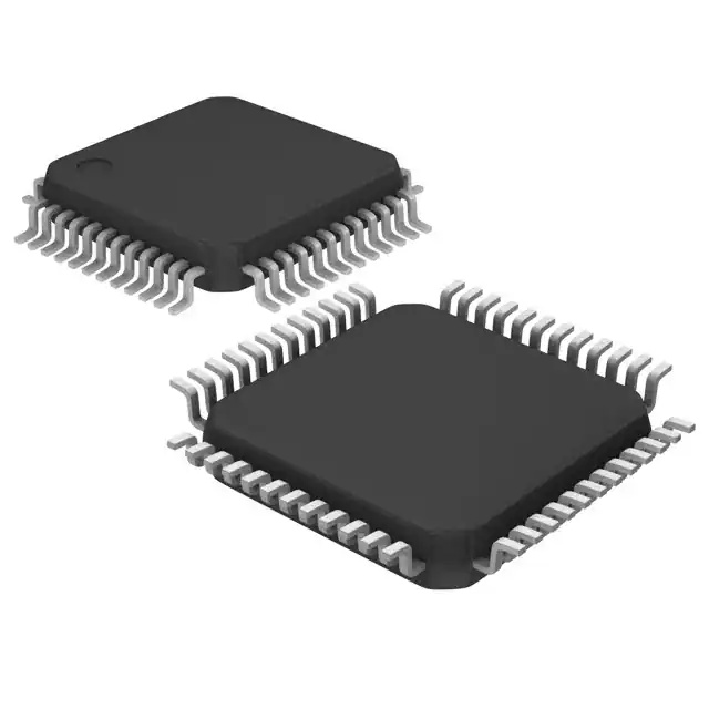
Figure1: Stm32f103c8
Ⅱ Stm32f103c8 Pinout
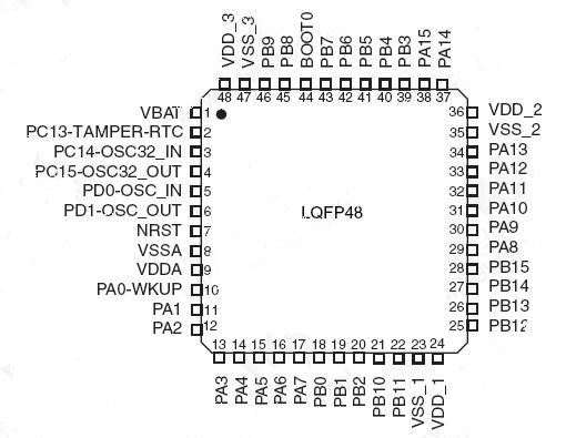
Figure2: Stm32f103c8 Pinout
Ⅲ Stm32f103c8 CAD Model
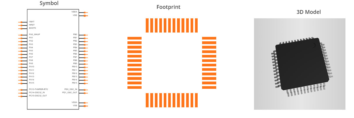
Figure3: Stm32f103c8 CAD Model
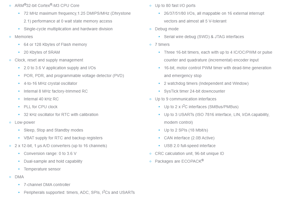
Ⅳ Stm32f103c8 Features
Ⅴ Stm32f103c8 Specification
|
Product Attribute |
Attribute Value |
|
Manufacturer: |
STMicroelectronics |
|
Product Category: |
ARM Microcontrollers - MCU |
|
Series: |
STM32F103C8 |
|
Mounting Style: |
SMD/SMT |
|
Package / Case: |
LQFP-48 |
|
Core: |
ARM Cortex M3 |
|
Program Memory Size: |
64 kB |
|
Data Bus Width: |
32 bit |
|
ADC Resolution: |
12 bit |
|
Maximum Clock Frequency: |
72 MHz |
|
Number of I/Os: |
37 I/O |
|
Data RAM Size: |
20 kB |
|
Supply Voltage - Min: |
2 V |
|
Supply Voltage - Max: |
3.6 V |
|
Minimum Operating Temperature: |
- 40 C |
|
Maximum Operating Temperature: |
+ 85 C |
|
Packaging: |
Tray |
|
Brand: |
STMicroelectronics |
|
Data RAM Type: |
SRAM |
|
Height: |
1.4 mm |
|
Interface Type: |
CAN, I2C, SPI, USART, USB |
|
Length: |
7 mm |
|
Moisture Sensitive: |
Yes |
|
Number of ADC Channels: |
10 Channel |
|
Number of Timers/Counters: |
3 Timer |
|
Processor Series: |
ARM Cortex M |
|
Product: |
MCU |
|
Product Type: |
ARM Microcontrollers - MCU |
|
Program Memory Type: |
Flash |
|
Factory Pack Quantity: |
1500 |
|
Subcategory: |
Microcontrollers - MCU |
|
Tradename: |
STM32 |
|
Width: |
7 mm |
|
Unit Weight: |
0.006349 oz |
Ⅵ Stm32f103c8 Application
- Motor drive and application control
- Medical and handheld equipment
- PC peripherals gaming and GPS platforms
- Industrial applications: PLC, inverters, printers, and scanners
- Alarm systems, Video intercom, and HVAC
Ⅶ How to measure analog voltage with ADC in STM32F103C8?
A common feature used in almost every embedded application is the ADC module (Analog to Digital Converter). These ADCs can read voltages from analog sensors like temperature sensors, tilt sensors, current sensors, bend sensors, etc. Now, we learn how to use the ADC in STM32F103C8 to read the analog voltage. We connect a potentiometer to the STM32 Blue Pill board, change the resistance of the potentiometer to provide different voltages for the ADC and display the read voltage on the 1602 LCD.
7.1 ADC in STM32F103C8
There is a 10-channel, 12-bit ADC in the STM32F103C8 with an input range of 0V-3.3V. It maps an input voltage between 0 and 3.3 volts to an integer value between 0 and 4095. The term 10 channels here means that there are 10 ADC pins available for measuring analog voltages. The term 12 bits refers to the resolution of the ADC, meaning 000000000000-111111111111 (212 is 4096). This is the number of sampling steps for our ADC, so our ADC values range from 0 to 4095. The value will increase from 0 to 4095 based on the voltage value per step, which can be calculated in terms of voltage/steps = reference voltage / 4096 = (3.3/4096= 8.056mV) per unit.
7.2 How Analog Signals Are Converted to Digital Format?
Since computers only store and process binary/digital values (1 and 0). Therefore, an analog signal, such as a sensor's volt output, must be converted to a digital value for processing, and the conversion needs to be accurate. When an input analog voltage is provided to the STM32 at an analog input, the analog value is read and stored in an integer variable. The stored analog value (0-3.3V) is converted to an integer value (0-4096) using: Input Voltage = (ADC Value / ADC Resolution) * Reference Voltage Resolution = 4096 Reference Voltage = 3.3VSTM32F103C8T6 ADC Pins There are 10 ADC pins in STM32, from PA0 to PB1.
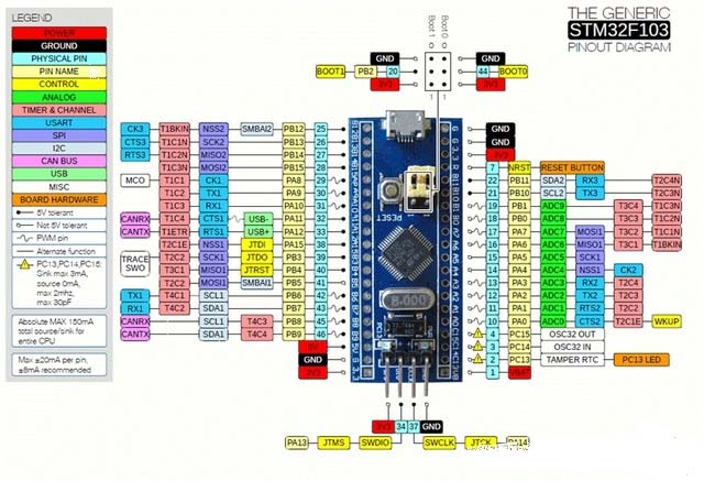
Figure5: STM32F103C8T6 ADC Pins
7.3 Circuit Diagram
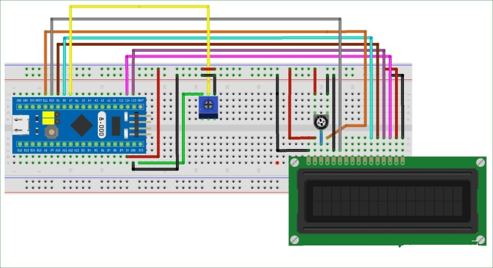
Figure6:Circuit Diagram
7.4 LCD and STM32 connection
|
LCD(number) |
LCD(pin) |
STM32(pin) |
|
1 |
GND |
GND |
|
2 |
VCC |
5V |
|
3 |
VEE |
The pin in the center of the potentiometer |
|
4 |
RS |
PB11 |
|
5 |
RW |
GND |
|
6 |
E |
PB10 |
|
7 |
D0 |
|
|
8 |
D1 |
|
|
9 |
D2 |
|
|
10 |
D3 |
|
|
11 |
D4 |
PB0 |
|
12 |
D5 |
PB1 |
|
13 |
D6 |
PC13 |
|
14 |
D7 |
PC14 |
|
15 |
A(LCD Backlight cathode) |
5V |
|
16 |
K(LCD Backlight Negative) |
GND |
The 1602 LCD is connected according to the table above. There are two potentiometers in the circuit, the first one is used as a voltage divider to change the voltage and provide an analog input to the STM32. The left pin of this potentiometer gets input positive voltage from STM32 (3.3V), the right pin is grounded, and the center pin of the potentiometer is connected to the analog input pin (PA7) of STM32. Another potentiometer is used to change the contrast of the LCD. The STM32 is powered by the PC's USB power supply.
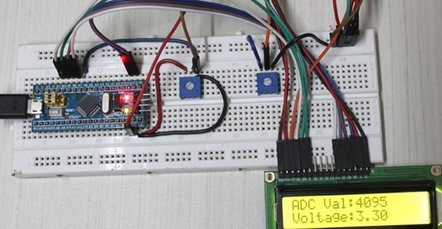
Figure7: LCD and STM32 connection
7.5 Programming the STM32 to read ADC values
Connect the STM32 to a PC via its USB port and start programming with the ARDUINO IDE. In the program, read the analog value and use that to calculate the voltage, then display the analog and digital values on the LCD screen.
#include <LiquidCrystal.h> // LCD library
//First define the LCD pins. These define to which pin of the STM32 the LCD pin is connected.
// You can modify it according to your requirements.
const int rs = PB11, en = PB10, d4 = PB0, d5 = PB1, d6 = PC13, d7 = PC14;
LiquidCrystal lcd(rs, en, d4, d5, d6, d7); //Initialize LCD
const int analogip = PA7;//analog input pin
void setup()
{
lcd.begin(16, 2); //We are using 16*2 LCD
lcd.clear(); // clear screen
lcd.setCursor(0, 0); //Set the cursor on the first row and first column
lcd.print("Hello World!"); //LCD displays this
lcd.print("STM32F103C8"); //LCD displays this column
lcd.print("STM32F103C8"); //LCD displays this
delay(2000);//wait for two seconds
lcd.clear(); // clear screen
lcd.setCursor(0, 0); //Set the cursor on the first row and first column
lcd.print("USING ADC IN");//print this
lcd.setCursor(0,1); //Set the cursor in the second row and first column
lcd.print("STM32F103C8");//print this
delay(2000); //wait for two seconds
lcd.clear(); // clear screen
}
void loop()
{
int val = analogRead(PA7); // read ADC value from pin A7
float voltage = (float(val)/4096) * 3.3; // convert ADC value to voltage value
lcd.setCursor(0, 0); // set the cursor to column 0, row 0
- print("ADC Val:");
lcd.print(val); //Display ADC value
lcd.setCursor(0, 1); // set the cursor to column 0, row 1
- print("Voltage:");
lcd.print(voltage);//display voltage
}
Ⅷ Stm32f103c8 PDF
 DC-DC converter RFB-0505S: Specification,Datasheet,Features and Applications6/13/2024 584
The RFB-0505S is a DC-DC converter from RECOM Power, Inc., belonging to the RFB Series. It features a Single In-Line Package (SIP7) and provides a single unregulated output. This converter offers 1 watt of power with an output voltage of 5V and is rated for an isolation voltage of 1kV.
Read More > Understanding the RFMM-0505S DC-DC Converter: A Comprehensive Guide6/4/2024 758
In the world of electronics, ensuring efficient power management is crucial for the performance and reliability of devices. One of the key components in achieving this is the DC-DC converter. Today, we dive into the specifics of the RFMM-0505S DC-DC converter, exploring its features, applications, and benefits.
Read More > 12V DC-DC Converter AM2G-0512SZ: Specifications, Datasheet, Applications and Features6/3/2024 676
A DC-DC converter is an essential electronic device to convert a direct current (DC) source from one voltage level to another. These converters are widely employed in various applications, including portable electronic devices, automotive systems, and renewable energy installations.
Read More > What is LM3900 Quadruple Norton Operational Amplifier?5/30/2024 1356
The LM3900 consists of four independent dual-input internally compensated amplifiers. These amplifiers are specifically designed to operate on a single power supply voltage and provide a large output voltage swing. They utilize current mirrors to achieve in-phase input functionality. Applications include AC amplifiers, RC active filters, low-frequency triangle waves, square wave, and pulse waveform generation circuits, tachometers, and low-speed, high-voltage digital logic gates.
Read More > Exploring the MMBT3906 Transistor: A Comprehensive Guide5/24/2024 978
The goal of the Taiwan Semiconductor MMBT3906 PNP Bipolar Transistor is to provide a high surge current capability with minimal power loss. This transistor is perfect for automated installation and has high efficiency.
Read More >
SUPPORT
ABOUT BITFOIC
QUICK LINKS
Connect with us
Tel: 86-755-23606554
E-mail: [email protected]
Address: Room A29, 24 / F, Hoi Tak Wai, Prince Edward industrial building, 706 Prince Edward Road East, San Po Kong, Kowloon,Hongkong
Mon-Fri: 09.30 AM - 18.30 PM


