


TIP122 Transistor : Pinout, CAD Model, Circuit and Datasheet
Due to its unique characteristics, the TIP122 is a common-purpose transistor in the electronics industry. Examples of some of these characteristics are its remarkable current gain capability and a significant collector current of 5A. This transistor's design is unique since it can perform power switching and amplification tasks. This post explains the pinout, equivalent, uses, and features of the TIP122 transistor. An excellent transistor to utilize as a high-gain switch or amplifier is the TIP22 Darlington pair transistor, which is produced in a TO-220 package.
How to make Mini Amplifier using only one Transistor || TIP122 || Super Bass
Catalog
Ⅰ What is TIP122 Darlington NPN Transistor?
TIP122 is a Darlington Pair NPN Transistor, consisting of a pair of Darlington transistors, it works like a normal NPN transistor. Known for its high current gain of 1000, the TIP122 uses a very high current at the collector, i.e. 5 A. Due to the high current gain and large collector current (IC) of the TIP122, it is often used in loads using high currents and such circuits that require high amplification. The TIP122 consumes only 5 V between the base and emitter.
Ⅱ Tip122 Pinout
The TIP122 triode (transistor) pin diagram includes three pins, each pin and its function will be introduced below.
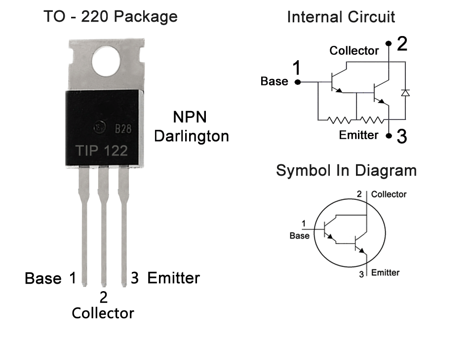
Figure1-tip122 pinout
Ⅲ TIP122 Transistor Pinout Configuration
|
Pin Number |
Pin Name |
Description |
|
1 |
Base |
Controls the biasing of the transistor, Used to turn ON or OFF the transistor |
|
2 |
Collector |
Current flows in through the collector, normally connected to load |
|
3 |
Emitter |
Current Drains out through emitter, normally connected to ground |
Ⅳ TIP122 CAD Model
Symobol

Figure2-Symobol
Footprint
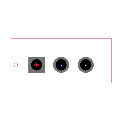
Figure3-Footprint
3D Model
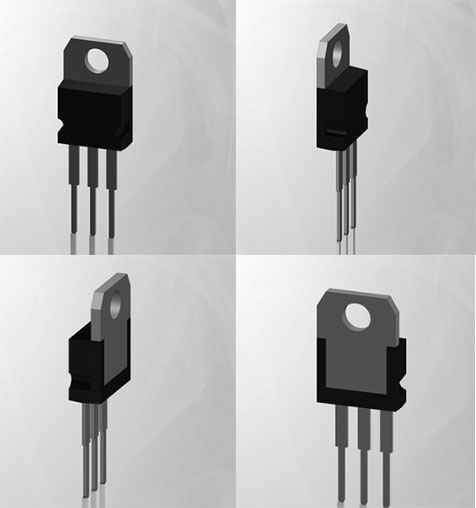
Figure4-3D Model
Ⅴ Characteristics of TIP122 Transistor
- Type: NPN
- Collector-Emitter Voltage, max: 100V
- Collector-Base Voltage, max: 100V
- Emitter-Base Voltage, max: 5V
- Collector Current − Continuous, max: 5A
- Collector Dissipation: 65W
- DC Current Gain (hfe): 1000
- Operating and Storage Junction Temperature Range: -65 to +150°C
- Package: TO-220
Ⅵ TIP122 Working Principle (Internal Schematic)
The internal circuit diagram of the TIP122 transistor clearly shows the Darlington pairs inside. As shown in the figure below, the TIP122 TO-220 package has two transistors, the emitter of the first transistor is connected to the base of the second transistor, and the collectors of the two transistors are coupled to form a Darlington pair, which improves the transistor’s Current gain and current rating.
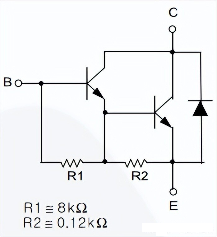
Figure5-working principle
Ⅶ TIP122 Replacement
- TIP122 equivalent model
TIP132, TIP102, NTE261, NTE263, 2N6045, 2N6045G, 2SD2495, BDT65B, 2N6532, BDT63B, BDW43, TIP142T. The pin configuration of some transistors may be different from TIP122, please check the pin configuration before replacing the circuit.
- TIP122 Complementary Model
TIP127
- TIP122 same type:
NPN:TIP120、TIP121、TIP122
PNP:TIP125、TIP126、TIP127
- TIP122 Replacement
BC547、BC548、BC549、BC636、BC639、2N2369、2N3055、2N3904、2N3906、2SC5200
Ⅷ How to use TIP0122?
TIP122 working principle analog circuit diagram
Although the TIP122 has high collector current and current gain, its control is fairly simple as its emitter-base voltage (VBE) is only 5V and its base current is only 120mA. In the circuit below, the TIP122 is used to control a 48V motor with a continuous current of about 3A.
The TIP122 transistor has a continuous collector current of 5A, the load draws only 3A, and a maximum base current of about 120mA, but I used a high resistor value of 100ohm to limit it to 42mA. You could even use a 1K resistor if your collector current requirements are low.
The peak (pulse) current of the TIP122 transistor is 8A, so make sure your motor doesn't draw more than that.
This is just a model circuit diagram showing how this transistor works, but it cannot be used as such. So, similarly, you can control the load in the same way.
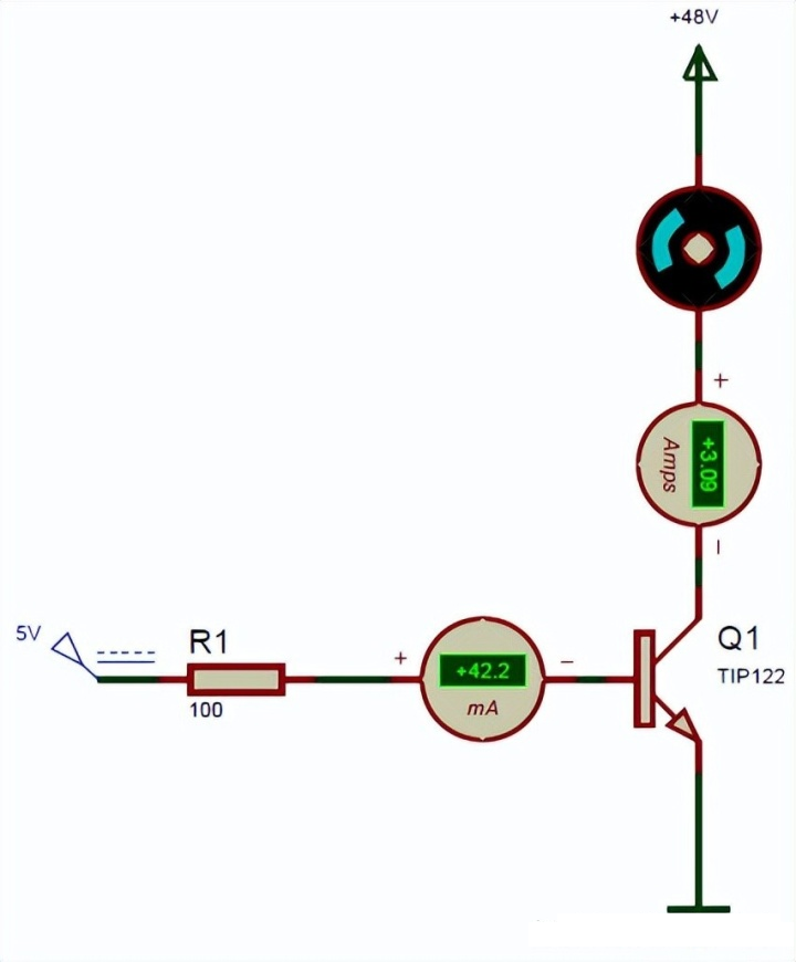
Figure6-model circuit diagram
Ⅸ Explanation of TIP122 Power Amplifier Circuit Diagram

Figure7-TIP122 Power Amplifier Circuit Diagram
Audio input is taken from a common audio converter, such as a microphone. This input is used as the DC control signal for transistor Q1. Here, a capacitor (470uF) acts as a coupling capacitor, blocking the DC component of the signal and allowing only the AC component of the signal to pass through. Transistor Q1 amplifies the signal and sends it to the base of transistor Q2, and the TIP122 further amplifies the input signal and directs it to an audio output device such as a speaker.
You can adjust the strength of the output audio signal by simply adjusting the 10K preset potentiometer.
The figure below is a list of components for building an audio amplifier circuit with a TIP122 Darlington transistor.
|
Number |
Components |
value |
quantity |
|
1 |
Darlington Pair NPN Transistor |
TIP122 |
2 |
|
2 |
audio jack |
3.5MM |
1 |
|
3 |
phone |
/ |
1 |
|
4 |
terminal block connector |
/ |
2 |
|
5 |
trumpet |
8Ω |
1 |
|
6 |
electric potential |
10k |
1 |
|
7 |
capacitance |
470uF |
1 |
|
8 |
resistance |
150k |
1 |
|
9 |
Jumper |
/ |
1 |
|
10 |
DC battery with clip |
/ |
Depends on requirements |
Ⅹ How to Safely Long Run in a Circuit?
To get better performance with this Darlington transistor we suggest always staying below its maximum ratings. Do not operate it in circuits using more than 100V. Do not provide a load of more than 5A. Always use a suitable base resistor to provide the required current at its base. Use a suitable heatsink to save it from overheating and store or use it in temperatures below -65 centigrade and above +150 centigrade.
Ⅺ TIP122 Applications
- Can be used to switch high-current (upto 5A) loads
- Can be used as medium Power switches
- Used where high amplification is needed
- Speed control of Motors
- Inverter and other rectifier circuits
Ⅻ Advantages and Disadvantages of TIP122
Advantages
- Provides extremely high current gain compared to a single transistor.
- Offers lower noise than phototransistors that include an external amplifier.
- The input impedance provided is very high.
- By using current sources of a few milliamps, designers can drive more power-based applications.
- Use fewer components to make circuits.
- Very sensitive to current.
- Signal amplification can be done for a long time.
Disadvantages
- Once the transistor is in the saturation region, there is a voltage drop across the BE terminal.
- The leakage current of the first transistor can be amplified by the second transistor.
- Darlington transistors have a higher overall outflow current.
- Switching is slow.
- It provides maximum power dissipation due to high saturation voltage.
- Limited bandwidth.
- At certain frequencies, this design can introduce a phase shift in the negative feedback circuit.
XIII TIP122 2D-Model
2D dimensions will help you in placing this component at the time of making the circuit on a perf board or a PCB.
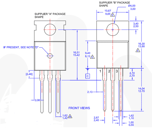
Figure8-2D-Model
XIV TIP122 PDF
 DC-DC converter RFB-0505S: Specification,Datasheet,Features and Applications6/13/2024 549
The RFB-0505S is a DC-DC converter from RECOM Power, Inc., belonging to the RFB Series. It features a Single In-Line Package (SIP7) and provides a single unregulated output. This converter offers 1 watt of power with an output voltage of 5V and is rated for an isolation voltage of 1kV.
Read More > Understanding the RFMM-0505S DC-DC Converter: A Comprehensive Guide6/4/2024 719
In the world of electronics, ensuring efficient power management is crucial for the performance and reliability of devices. One of the key components in achieving this is the DC-DC converter. Today, we dive into the specifics of the RFMM-0505S DC-DC converter, exploring its features, applications, and benefits.
Read More > 12V DC-DC Converter AM2G-0512SZ: Specifications, Datasheet, Applications and Features6/3/2024 644
A DC-DC converter is an essential electronic device to convert a direct current (DC) source from one voltage level to another. These converters are widely employed in various applications, including portable electronic devices, automotive systems, and renewable energy installations.
Read More > What is LM3900 Quadruple Norton Operational Amplifier?5/30/2024 1291
The LM3900 consists of four independent dual-input internally compensated amplifiers. These amplifiers are specifically designed to operate on a single power supply voltage and provide a large output voltage swing. They utilize current mirrors to achieve in-phase input functionality. Applications include AC amplifiers, RC active filters, low-frequency triangle waves, square wave, and pulse waveform generation circuits, tachometers, and low-speed, high-voltage digital logic gates.
Read More > Exploring the MMBT3906 Transistor: A Comprehensive Guide5/24/2024 919
The goal of the Taiwan Semiconductor MMBT3906 PNP Bipolar Transistor is to provide a high surge current capability with minimal power loss. This transistor is perfect for automated installation and has high efficiency.
Read More >
SUPPORT
ABOUT BITFOIC
QUICK LINKS
Connect with us
Tel: 86-755-23606554
E-mail: [email protected]
Address: Room A29, 24 / F, Hoi Tak Wai, Prince Edward industrial building, 706 Prince Edward Road East, San Po Kong, Kowloon,Hongkong
Mon-Fri: 09.30 AM - 18.30 PM


