


MMBT3904 Transistor Basic Knowledge: Pinout, CAD Model, Package, Application and Equivalent [FAQ]
NPN transistor is commonly used in circuits. This post will embody some basic knowledge of MMBT3904, an SMD package NPN transistor with a collector current of 200mA and a VCE of 40V.

Catalog
ⅠWhat is MMBT3904?
The collector and emitter of the surface-mounted NPN transistor BT3904 remain open (reverse-biased) when the base pin is grounded and are closed (forward-biased) when the base pin is receiving a signal. The BT3904 transistor's maximal gain, which is 300, specifies the transistor's capacity for amplification. This transistor cannot be used to connect loads that draw more than 200mA because the collector pin's maximum current is 200mA. We must deliver current (Ib) to the base pin in order to bias the transistor; this current should be kept to a maximum of 5 mA. There is a 200mA limit on the maximum current that can pass through the collector and emitter of this transistor when it is entirely biased. The voltage typically permitted to flow through the collector-emitter (Vce) or collector-base (Vcb) at this point, known as the saturation zone, is 40V or 60V, respectively. The transistor is completely disconnected once the base current has been removed. The cut-off region is the name of this phase. The voltage at the emitter-base (Veb) can be as high as 6V.
Ⅱ MMBT3904 Transistor Pinout
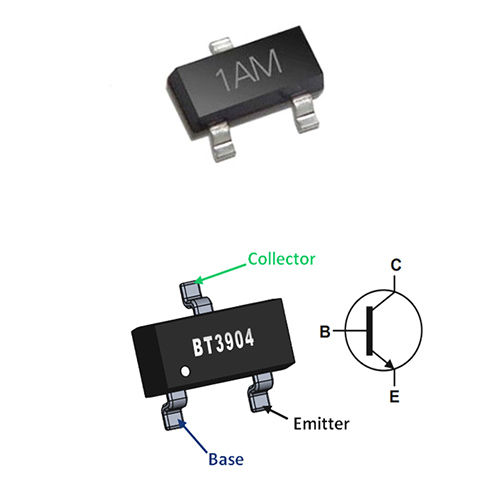
Figure1: MMBT3904 transistor pinout
Ⅲ Pin Configuration
|
Pin Number |
Pin Name |
Description |
|
1 |
Emitter |
Current flows out through Emitter |
|
2 |
Base |
Controls the biasing of the Transistor |
|
3 |
Collector |
Current flows in through Collector |
Ⅳ MMBT3904 CAD Model
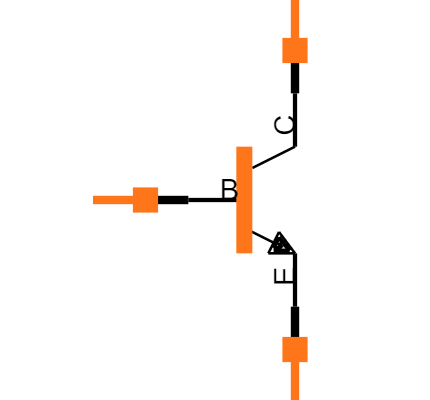
symbol
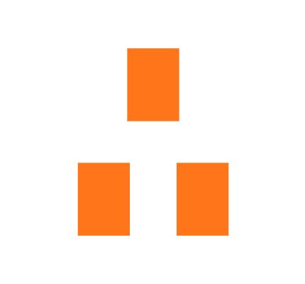
footprint
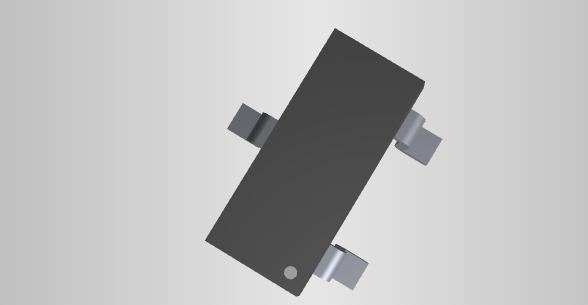
CAD Model
ⅤMMBT3904 SMD Transistor Electrical Specification
- MMBT3904 epitaxial planer NPN SMD transistor device
- Collector to emitter voltage is 40V
- Collector to base voltage is 60V
- Emitter to base voltage is 6V
- The collector current is 200mA
- Power dissipation is 310mW
- DC current gain is 30 to 300hFE
- Small signal current gain is 100 to 400hFE
- Current gain bandwidth (FT) is 300MHz
- The junction temperature is between-55 to 150℃
- Collector to emitter saturation voltage (VCE (SAT)) is20 to 0.30V
- Thermal resistance is 403℃/W
- Noise figure (NF) is 5dB
- Rise time (tr) is 35ns
Ⅵ MMBT3904 Features
- NPN small signal Transistor
- Continuous Collector Current (Ic) is 200mA
- Collector to Emitter Voltage (VCE) is 40V
- Emitter to Base Voltage (VEB) is 6V
- Current Gain (hfe) is 100 to 300
- Transition frequency: 300MHz
- Available in SOT23 SMD package
Note: The complete technical information can be found on the datasheet given at the end of this page.
Ⅶ MMBT3904 Applications
- Driver Modules like Relay Driver, LED driver, etc...
- Amplifier modules like Audio amplifiers, signal Amplifiers, etc...
- VCB and VBE are high and hence can be used to control voltage loads up to 40V
- Commonly used in TV and other home appliances
Ⅷ MMBT3904 SMD/SMT Transistor Equivalent
FMMT2222A, MMBT3904LT1G, MMBT4401, MMBTA05, MMBTA06
Most of the SMD transistor equivalents have almost the same electrical specs, this is the reason why we can easily replace them.
SMD or SMT transistor devices had to check the power dissipation and packaging details, it is very important for the replacement process.
Ⅸ MMBT3904 Package Dimensions
MMBT3904 is an SMD transistor, available in the SOT-23 package. The dimensions of the SOT-23 Package is shown below.
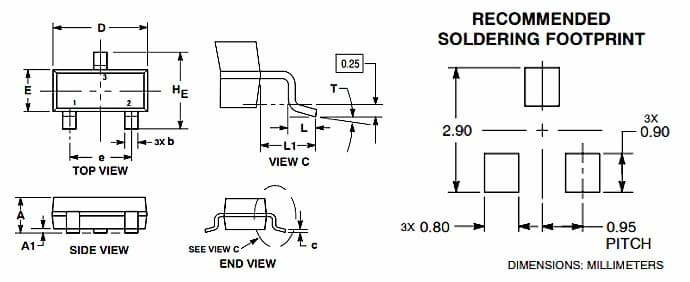
Figure2: MMBT3904 SOT-23 Package
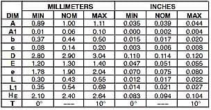 Figure3: MMBT3904 SOT-23 Package
Ⅹ MMBT3904 vs MMBT4401 vs MMBT100
In this table we try to list the electrical specs of each MMBT3904 vs MMBT4401 vs MMBT100, this comparison will be really helpful for replacement.
|
Characteristics |
MMBT3904 |
MMBT4401 |
MMBT100 |
|
Collector to base voltage (VCB) |
60V |
60V |
75V |
|
Collector to emitter voltage (VCE) |
40V |
40V |
45V |
|
Emitter to base voltage (VEB) |
6V |
6V |
6V |
|
Collector to emitter saturation voltage (VCE (SAT)) |
0.20 to 0.30V |
0.73V |
0.4V |
|
Collector current (IC) |
200mA |
0.6A |
500mA |
|
Power dissipation |
310mW |
0.35W |
350mW |
|
Junction temperature (TJ) |
-55 to +150°C |
150°C |
150°C |
|
Transition frequency (FT) |
300MHZ |
250MHZ |
250MHZ |
|
Gain (hFE) |
30 to 300hFE |
100 to 300hFE |
80 to 450hFE |
|
Small signal current gain |
100 to 400hFE |
40 to 500hFE |
- |
|
Rise time (tr) |
35ns |
20ns |
- |
|
Noise figure (NF) |
5dB |
- |
5dB |
|
Package |
SOT-23 |
SOT-23 |
SOT-23 |
Showing 1 to 13 of 13 entries
The terminal voltage specs of each transistor are the same, the saturation voltage is considered as the switching of the transistor from one state to another, this value is slightly different for each of these SMD transistors.
The amplification quantities such as current gain, transition frequency, and noise frequency will be almost the same, this shows that we can use each of these three SMD transistors as the equivalents.
Ⅺ MMBT3904 SMD Transistor Characteristics
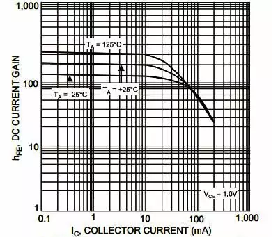
Figure4: DC current gain vs collector current characteristics
The figure shows the DC current gain vs collector current characteristics, at these characteristics temperature capacity of the device, had a major role to play.
At a constant collector-to-emitter voltage, the current gain of the device will start at a certain limit and decreases at the end.
The collector current starts to increase till the time device started and then reaches the maximum limit.
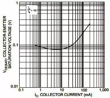
Figure: Collector to emitter saturation voltage vs collector current characteristics
The figure shows the collector-to-emitter saturation voltage vs collector current characteristics, the graph plotted an inverted parabolic shape for these characteristics.
This means both the collector-to-emitter saturation voltage and collector current started low and also they started increasing after a slight time gap.
Ⅻ MMBT3904 Transistor PDF
 DC-DC converter RFB-0505S: Specification,Datasheet,Features and Applications6/13/2024 549
The RFB-0505S is a DC-DC converter from RECOM Power, Inc., belonging to the RFB Series. It features a Single In-Line Package (SIP7) and provides a single unregulated output. This converter offers 1 watt of power with an output voltage of 5V and is rated for an isolation voltage of 1kV.
Read More > Understanding the RFMM-0505S DC-DC Converter: A Comprehensive Guide6/4/2024 719
In the world of electronics, ensuring efficient power management is crucial for the performance and reliability of devices. One of the key components in achieving this is the DC-DC converter. Today, we dive into the specifics of the RFMM-0505S DC-DC converter, exploring its features, applications, and benefits.
Read More > 12V DC-DC Converter AM2G-0512SZ: Specifications, Datasheet, Applications and Features6/3/2024 644
A DC-DC converter is an essential electronic device to convert a direct current (DC) source from one voltage level to another. These converters are widely employed in various applications, including portable electronic devices, automotive systems, and renewable energy installations.
Read More > What is LM3900 Quadruple Norton Operational Amplifier?5/30/2024 1289
The LM3900 consists of four independent dual-input internally compensated amplifiers. These amplifiers are specifically designed to operate on a single power supply voltage and provide a large output voltage swing. They utilize current mirrors to achieve in-phase input functionality. Applications include AC amplifiers, RC active filters, low-frequency triangle waves, square wave, and pulse waveform generation circuits, tachometers, and low-speed, high-voltage digital logic gates.
Read More > Exploring the MMBT3906 Transistor: A Comprehensive Guide5/24/2024 919
The goal of the Taiwan Semiconductor MMBT3906 PNP Bipolar Transistor is to provide a high surge current capability with minimal power loss. This transistor is perfect for automated installation and has high efficiency.
Read More >
SUPPORT
ABOUT BITFOIC
QUICK LINKS
Connect with us
Tel: 86-755-23606554
E-mail: [email protected]
Address: Room A29, 24 / F, Hoi Tak Wai, Prince Edward industrial building, 706 Prince Edward Road East, San Po Kong, Kowloon,Hongkong
Mon-Fri: 09.30 AM - 18.30 PM


