


MIC29302 3A Adjustable LDO Regulator: Pinout, Applications Features, Working Principle and Circuit Example
Introduction
The MIC29150/29300/29500/29750 are high-current, high-accuracy, low-dropout voltage regulators. Using the proprietary Super βeta PNP® process with a PNP pass element, these regulators feature 350mV to 425mV (full load) typical dropout voltages and very low ground current. Designed for high-current loads, these devices also find applications in lower-current, extremely low dropout-critical systems, where their tiny dropout voltage and ground current values are important attributes. This post will introduce you to the basic information about MIC29302 Linear Regulators.
Catalog
Ⅰ What is MIC29302 3A Adjustable LDO Regulator?
The MIC29302 is an LDO (Low Drop Out) variable voltage regulator from Microchip, meaning it is capable of regulating voltage efficiently without dropping much voltage across the regulator and can provide output voltage almost close to the input voltage. The regulator has a maximum output current of 3A during which it drop-out voltage across the regulator is only 450mA. The input voltage of the Regulator can be between 3V to 16V and the output voltage can be configured between 1.24V to 15V by using a couple of resistors.
The regulator comes with an Enable pin to provide Zero-current shutdown mode making it suitable for designs demanding high efficiencies like battery-powered equipment and linear voltage supplies. Therefore, If you are looking for regulators that operate on further low voltage then consider the MIC37xxx series LDO regulators.
Ⅱ MIC29302 Pinout
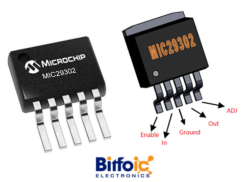
Figure1-MIC29302 Pinout
Ⅲ Pin Configuration
|
Pin Number |
Pin Name |
Description |
|
1 |
Enable |
TTL logic pin to turn on/off the regulator |
|
2 |
In |
Input voltage that is to be regulated |
|
3 |
Ground |
Connected to system ground |
|
4 |
out |
Regulated Output Voltage |
|
5 |
Adjust |
Sets the output voltage using two resistor divider network |
Ⅳ MIC29302 Features
- High Current Capability:
- MIC29150/29151/29152/29153: 1.5A
- MIC29300/29301/29302/29303: 3A
- MIC29500/29501/29502/29503: 5A
- MIC29751/29752: 7.5A
- Low Dropout Voltage
- Low Ground Current
- Accurate 1% Guaranteed Tolerance
- Extremely Fast Transient Response
- Reverse-Battery and “Load Dump” Protection
- Zero-Current Shutdown Mode (5-Pin Versions)
- Error Flag Signals Output Out-of-Regulation (5-Pin Versions)
- Also Characterized for Smaller Loads with Industry-Leading Performance Specifications
- Fixed-Voltage and Adjustable Versions
Ⅴ MIC29302 Applications
- Battery-Powered Equipment
- High-Efficiency Green Computer Systems
- Automotive Electronics
- High-Efficiency Linear Power Supplies
- High-Efficiency Post-Regulator for Switching Supply
Ⅵ MIC29302 Working Principle
6.1 The working principle of MIC29302
A voltage regulator has three main components, the pass element, error amplifier, and voltage reference. Usually, the pass element is an N-channel or P-channel FET, but in the MIC29302 regulator, it is a PNP transistor. The input voltage is applied to a PNP transistor connected to the error amplifier. This transistor works in the linear region/active region to step down the input voltage to the desired output voltage.
The error amplifier senses the resulting output voltage and compares it to a reference voltage. The error amplifier changes the transistor to the proper operating point to ensure the output is at the correct voltage. As the input voltage changes, the error amplifier modulates the transistor to maintain a constant output voltage.
This is how an LDO regulator or low dropout regulator circuit works and a block diagram of the MIC29302 regulator IC is below.
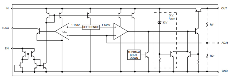
Figure 2- LDO regulator or low dropout regulator circuit works Source from circuitdigest.com
6.2 How to use MIC29302?
The output voltage of the MIC29302 IC regulator can be set simply by using two resistors of the desired value. The regulator comes in a 5-pin package where the enable pin can be turned on or off by the regulator, shutting down the regulator when not in use and preventing battery usage. The adjust pin is used to set the output voltage of the regulator to the desired value using the circuit below.
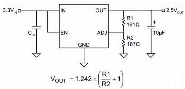
Figure3-How to use MIC29302
As you can see, the resistor values R1 and R2 determine the output voltage Vout of our controller. Cin and 10uF capacitors are used for filtering and ripple on the input or output side of the regulator. If the regulator is battery-powered, Cin is not needed. Depending on the current drawn from the regulator, the regulator's output voltage can vary from 150mV to a maximum of 450mV.
Ⅶ MIC29302 Regulator Parameters
1) Quiescent current
The term "quiescent" is defined as "a state or period of inactivity or dormancy". Therefore, quiescent current (IQ) is the current drawn by the system when it is connected to a light load or no load in standby mode. Both quiescent current and shutdown current are different terms; quiescent current is the current drawn by the system when a light load or no load is connected, while shutdown current is the current drawn when the device is off but the battery is still connected to the device.
2) Power Supply Rejection Ratio (PSRR)
PSRR is defined as the ability to reject AC elements such as ripple voltage. Expressed by the following formula:
PSRR (dB): 20 logs (V ripple (input) /V ripple (output))
3) Load regulation
Load regulation is defined as the ability of a circuit to maintain a specified output voltage under varying load conditions. Load regulation is expressed as:
Load regulation = ∆Vout/ ∆I out
4) Line Adjustment
Line regulation is defined as the ability of a circuit to maintain a specified output voltage as the input voltage varies. Line regulation is expressed as:
Load Regulation = ∆V out / ∆V in
5) Transient response
Transient response is defined as the maximum allowable output voltage change for a step change in load current. It is also known as line step response. The transient response is a function of the output capacitor value (C out ), the equivalent series resistance (ESR) of the output capacitor, the bypass capacitor (C b ), and the maximum load current (I out, max ). The maximum transient voltage change is expressed as:
∆V tr, max = (I out, max / C out + C b ) ∆t 1 + ∆V ESR
6) Undervoltage lockout
When the input voltage is lower than the specified input voltage, this function puts the IC into a standby state, making the internal circuit unstable without damaging the IC.
7) Current limit
Excessive heat generated by the device during operation can damage the IC and degrade its performance. A current limit feature protects the device from overheating. There are two current limiting methods: the first is a foldback type that reduces both the output current and output voltage, and the second is a current limiter type that reduces the output voltage while keeping the output current constant.
8) Thermal Shutdown (TSD)
Sometimes due to an unintentional high current load or some other reason, the temperature of the device rises very fast and can damage the IC. The thermal shutdown function is used to prevent device degradation and damage due to a significant increase in ambient temperature. When the internal temperature detection circuit detects a high temperature, it turns off the output transistor.
9) Output Discharge
When the output transistor is turned off by the internal temperature detection circuit due to high temperature, the Vout terminal voltage may remain for a while, depending on the load capacitance. The output discharge circuit is used to quickly discharge the charge and drop the V out terminal voltage close to IC GND.
Ⅷ MIC29302 Alternative
Equivalent for MIC29302: MIC29300, MIC29500, MIC29750
Alternative LDO Regulators: LP2985, AMS1117, MIC5225
Ⅸ MIC29302 Voltage Regulator Circuit Example
In the following circuit, we will use the MIC29302 to build an LDO regulator or low dropout regulator circuit. The output voltage can be varied using a high or low-value resistor on the adjust pin.
- Required components
MIC29302 voltage regulator
Resistance (1KΩ)
Potential (10K)
Capacitance (10µf and 0.1µf)
Power supply (12V)
- Circuit diagram

Figure 4-Circuit diagram Source from: circuitdigest.com
- How to work?
This low dropout regulator circuit requires very few components. In this circuit, we are only using two resistors and two capacitors. Capacitor C1 is connected to the Vin pin of the MIC29302 regulator IC for filtering the DC input voltage. Two external resistors R1 and RV1 are connected to the adjust pin and Vout pin of the IC. Resistors R1 and RV1 determine the output voltage Vout of the regulator. A 10uF capacitor at the output is used for stability and minimum output noise.
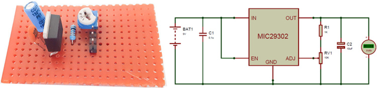
Figure 5-low dropout regulator circuit Source from circuitdigest.com
Ⅹ MIC29302 Package
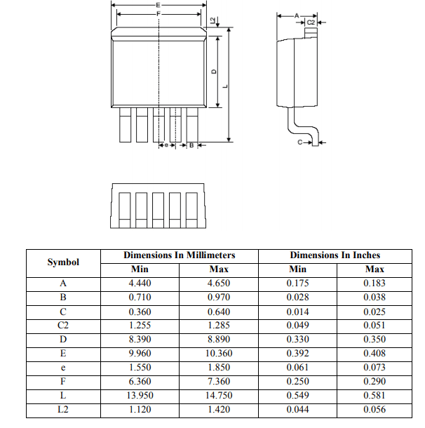
Figure 6-MIC29302 Package Source from circuitdigest.com
Ⅺ MIC29302 PDF
 DC-DC converter RFB-0505S: Specification,Datasheet,Features and Applications6/13/2024 469
The RFB-0505S is a DC-DC converter from RECOM Power, Inc., belonging to the RFB Series. It features a Single In-Line Package (SIP7) and provides a single unregulated output. This converter offers 1 watt of power with an output voltage of 5V and is rated for an isolation voltage of 1kV.
Read More > Understanding the RFMM-0505S DC-DC Converter: A Comprehensive Guide6/4/2024 655
In the world of electronics, ensuring efficient power management is crucial for the performance and reliability of devices. One of the key components in achieving this is the DC-DC converter. Today, we dive into the specifics of the RFMM-0505S DC-DC converter, exploring its features, applications, and benefits.
Read More > 12V DC-DC Converter AM2G-0512SZ: Specifications, Datasheet, Applications and Features6/3/2024 552
A DC-DC converter is an essential electronic device to convert a direct current (DC) source from one voltage level to another. These converters are widely employed in various applications, including portable electronic devices, automotive systems, and renewable energy installations.
Read More > What is LM3900 Quadruple Norton Operational Amplifier?5/30/2024 1152
The LM3900 consists of four independent dual-input internally compensated amplifiers. These amplifiers are specifically designed to operate on a single power supply voltage and provide a large output voltage swing. They utilize current mirrors to achieve in-phase input functionality. Applications include AC amplifiers, RC active filters, low-frequency triangle waves, square wave, and pulse waveform generation circuits, tachometers, and low-speed, high-voltage digital logic gates.
Read More > Exploring the MMBT3906 Transistor: A Comprehensive Guide5/24/2024 804
The goal of the Taiwan Semiconductor MMBT3906 PNP Bipolar Transistor is to provide a high surge current capability with minimal power loss. This transistor is perfect for automated installation and has high efficiency.
Read More >
SUPPORT
ABOUT BITFOIC
QUICK LINKS
Connect with us
Tel: 86-755-23606554
E-mail: [email protected]
Address: Room A29, 24 / F, Hoi Tak Wai, Prince Edward industrial building, 706 Prince Edward Road East, San Po Kong, Kowloon,Hongkong
Mon-Fri: 09.30 AM - 18.30 PM


