


Do you Know BD140 PNP Transistor: Pinout, Datasheet, Features and Applications
This blog discusses the pinout, equivalent, uses characteristics, and applications of the BD140 transistor in addition to other helpful details on when and where to utilize it.
Catalog
Ⅰ BD140 PNP Transistor Overview:
With its high collector-emitter and collector base voltage of 80 volts, the BD140 is a well-known PNP-type transistor that is used in many electronic circuits. It can handle current up to 1.5A or 1500mA, which enables it to be used to drive loads up to 1.5A in electronic circuits, such as high-power LEDs, relays, motors, and more. In addition to these features, the BD140 has a number of other advantages. Additionally, this transistor has a collector dissipation of about 12.5 watts, making it a strong choice for audio amplifier circuits. The transistor's minimal base voltage, also known as its saturation value, is -0.5V.
Ⅱ BD140 PNP Transistor Pinout
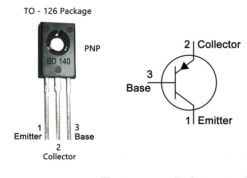
Figure1: bd140 pinout
Ⅲ BD140 Pinout Configuration
|
Pin Number |
Pin Name |
Pin Description |
|
1 |
Emitter |
Current Drains out through emitter, normally connected to ground |
|
2 |
Collector |
Current flows in through collector, normally connected to load |
|
3 |
Base |
Controls the biasing of the transistor, used to turn the ON or OFF the transistor. |
Ⅳ Features and Specifications
- Bi-Polar PNP Transistor
- Continuous Collector current (IC) is -1.5A
- Collector-Emitter voltage (VCE) is- 80 V
- Collector-Base voltage (VCB) is- 80V
- Base Current (Ib) is -0.5A
- DC current gain (hfe) is 40 to 160
- Available in To-225 and SOT-32 Package
- Collector Dissipation: 12.5 W
- Package Type: TO-126
- Max Collector Current(IC): -1.5A
- Max Emitter-Base Voltage (VEBO): –5V
- Max Transition Frequency (fT): 190 MHz
- Minimum & Maximum DC Current Gain (hFE): 25 – 250
- Max Storage & Operating temperature Should Be: -55 to +150 Centigrade
Ⅴ BD140 Equivalent Transistors
We can replaced this transistor with BD238G, MJE171, MJE702, BD792, BD170,BD180,BD231, BD790,BD792, BD792
Ⅵ Applications
Audio Amplifiers
Switching Loads under 1.5A
Battery Chargers
Power Supplies
Motor Driver
Darlington Pair
Ⅶ Bd140 vs bd139 vs bd136 vs mje702
The transistor in the table is a list of transistors that is similar to the bd140 transistor, this comparison table will give you a wider idea about the electrical characteristics of each transistor.
At the list, we compare bd140 vs bd139, both of the transistors are the complementary pair, and then bd136 vs mje702, most of the electrical specifications of these transistors are similar to bd140.
|
Characteristics |
Bd140 |
Bd139 (NPN) |
Bd136 |
Mje702 |
|
Collector to base voltage (VCB) |
-80V |
80V |
-45V |
-80V |
|
Collector to emitter voltage (VCE) |
-80V |
80V |
-45V |
-80V |
|
Emitter to base voltage (VEB) |
-5V |
5V |
-5V |
-5V |
|
Collector current (IC) |
-1.5A |
1.5A |
-1.5A |
-4A |
|
Power dissipation |
12.5W |
12.5W |
12.5W |
40W |
|
Junction temperature (TJ) |
150°C |
150°C |
150°C |
150°C |
|
Transition frequency (FT) |
190MHZ |
190MHZ |
190MHZ |
- |
|
Noise (N) |
- |
- |
- |
- |
|
Gain (hFE) |
25 to 250hFE |
25to 250hFE |
10 to 250hFE |
750Hfe |
|
Package |
TO-126 |
TO-126 |
TO-126 |
TO-126 |
Ⅷ Working principle of Bd140 Transistor
As mentioned Bd140 is a PNP transistor, so, in it the N-doped layer is embedded between two P-dopped layers. The collector and emitter are left closed when the base pin is held at the ground and are open when a signal is provided to the base pin. Since Bd140 is a PNP transistor so the majority of charge carriers are holes.
When no current is applied to the base terminal, then it will work in forward biased condition and it turns on. This condition is termed a Saturation Region.
When sufficient current is applied at the base terminal of this transistor, then it will work in Reverse biased condition and turns off. This situation is termed a cut-off region.
Ⅸ Where We Can Use it
BD140 is an ideal transistor to use in educational and hobby electronics projects for example in analog circuits, Arduino projects,, and other microcontroller projects. Moreover,, it is also used in industrial electronics. The maximum load this transistor can drive is 1.5A therefore it can be used to drive a variety of loads under 1.5A. When using this transistor for a load of more than 200mA it is recommended to use a suitable heatsink with it.
Ⅹ How to use BD140 Transistor
Transistors are current-controlled devices so to turn them on a little current is needed. For the BD140 Transistor, this base current is less than 10mA, as BD140 is a PNP transistor that means it will be on when the base is connected to the ground, and it will be off when a positive voltage is applied to the base of the transistor.
The simulated circuit below shows how this transistor behaves when the base of the basic circuit is connected to the ground and when it's connected to 12V of the power supply.
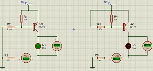
Figure2: simulated circuit
When we turn on the transistor by connecting the base to the ground the transistor will remain on unless the voltage at the base of the transistor reaches more than the base turn-off voltage, for this transistor, it is somewhere between 0.7 -0.9V. The base of the transistor cannot be left floating otherwise there could be false triggering, which may lead to issues in the circuit. To resolve this issue, we need to add pull-up resistors as shown in the example, a 10K resistor is used to pull up the base of the transistor to VCC.
Ⅺ How to Safely Long Run in a Circuit
To safely run this transistor in a circuit it is essential to not operate it above its absolute maximum ratings. Do not operate this transistor from a voltage higher than 80V DC, always use a suitable heatsink, and use a suitable base resistor to provide the required base current. Do not operate or store it in temperatures below -55 centigrade and above +150 centigrade.
Ⅻ Transistor Work as a Switch
As the BD140 is a bipolar junction transistor, so it is a current-controlled device i.e.a little current is applied at the base terminal to control the transistor. The BD140 is a PNP transistor, so it will be ON when the base terminal is connected to the ground, and it will be off when a positive voltage is applied to the base terminal of the transistor. The base current of this transistor is less than 10mA.
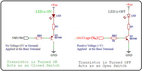
Figure3:BD140 Transistor Work as a Switch
XIII 2D Model and Dimensions
If you are designing a PCB or Perf board with this component, then the following picture from the Datasheet will be useful to know its package type and dimensions.
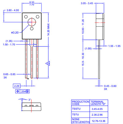
Figure4:2D Model and Dimensions
XIV BD140 TO-126 Package
The package used for the BD140 transistor in the TO-126 package is a rectangular-shaped transistor package.
Plastic and epoxy are used to make this TO-126 package, most of the time transistors with moderate current and high power dissipation use this transistor package.
The TO-126 transistor package weighs less and is compact to the device circuit, at the package we can spot a hole for attaching the heat sink into it.
XV BD140 PNP Transistor Datasheet
BD140 PNP Transistor Datasheet
 DC-DC converter RFB-0505S: Specification,Datasheet,Features and Applications6/13/2024 584
The RFB-0505S is a DC-DC converter from RECOM Power, Inc., belonging to the RFB Series. It features a Single In-Line Package (SIP7) and provides a single unregulated output. This converter offers 1 watt of power with an output voltage of 5V and is rated for an isolation voltage of 1kV.
Read More > Understanding the RFMM-0505S DC-DC Converter: A Comprehensive Guide6/4/2024 758
In the world of electronics, ensuring efficient power management is crucial for the performance and reliability of devices. One of the key components in achieving this is the DC-DC converter. Today, we dive into the specifics of the RFMM-0505S DC-DC converter, exploring its features, applications, and benefits.
Read More > 12V DC-DC Converter AM2G-0512SZ: Specifications, Datasheet, Applications and Features6/3/2024 676
A DC-DC converter is an essential electronic device to convert a direct current (DC) source from one voltage level to another. These converters are widely employed in various applications, including portable electronic devices, automotive systems, and renewable energy installations.
Read More > What is LM3900 Quadruple Norton Operational Amplifier?5/30/2024 1356
The LM3900 consists of four independent dual-input internally compensated amplifiers. These amplifiers are specifically designed to operate on a single power supply voltage and provide a large output voltage swing. They utilize current mirrors to achieve in-phase input functionality. Applications include AC amplifiers, RC active filters, low-frequency triangle waves, square wave, and pulse waveform generation circuits, tachometers, and low-speed, high-voltage digital logic gates.
Read More > Exploring the MMBT3906 Transistor: A Comprehensive Guide5/24/2024 978
The goal of the Taiwan Semiconductor MMBT3906 PNP Bipolar Transistor is to provide a high surge current capability with minimal power loss. This transistor is perfect for automated installation and has high efficiency.
Read More >
SUPPORT
ABOUT BITFOIC
QUICK LINKS
Connect with us
Tel: 86-755-23606554
E-mail: [email protected]
Address: Room A29, 24 / F, Hoi Tak Wai, Prince Edward industrial building, 706 Prince Edward Road East, San Po Kong, Kowloon,Hongkong
Mon-Fri: 09.30 AM - 18.30 PM


