


BME280 Sensor: Datasheet, Pinout and Applications
Introduction
In embedded products, we often need to detect ambient temperature, pressure, and humidity. It will undoubtedly be very convenient if there is a component that integrates these 3 sensors. Bosch's BME280 can fulfill this requirement. In this article, we will discuss the BME280 pinout, data storage format, interface, and other details.
Catalog
The BME280 is a combined digital humidity, pressure, and temperature sensor. The sensor module is placed in a remarkably small metal-lid LGA box, measuring just 2.5 x 1.5 mrn2 and 0.93 mm in height. The compact size and low power usage give it an advantage over other battery-powered gadgets like watches, GPS modules, and cell phones. The BME280 performs well in all applications that measure pressure and humidity. These new uses for GPS refinement, indoor navigation, fitness tracking, and home automation control demand both high accuracy and low TCO.
The humidity sensor provides an extremely fast response time for fast context awareness applications, the pressure sensor is a barometric pressure sensor with high accuracy and resolution. The integrated temperature sensor has the lowest noise and highest resolution. Its output is used for temperature compensation of the pressure and humidity sensors and can also be used for the estimation of the ambient temperature.
The sensor may be powered using 1.71 to 3.6 V for the sensor supply VCC and 1.2 to 3.6 V for the interface supply. The sensor offers both SPI and I2C interfaces. The host may initiate a measurement or it may happen at predetermined intervals. When the sensor is turned off, the current draw is reduced to 0.1 pm.
Ⅱ Hardware Description
The BME280 pressure, humidity, and temperature sensor realize high-performance temperature, pressure, and humidity detection, including three sensors of pressure, temperature, and humidity, a high-precision ADC and interface logic, and its structural block diagram is shown in the figure below:

Figure1-hardware description
Humidity sensors have extremely fast response times to meet the performance requirements of emerging applications such as environmental sensing and high accuracy over a wide temperature range. The pressure sensor is an absolute barometric pressure sensor with very high accuracy and resolution and very low noise. The integrated temperature sensor is optimized for extremely low noise and high resolution. It is mainly used for temperature compensation of pressure and humidity sensors, and can also be used to estimate the ambient temperature
Ⅲ BME280 Pinout
The BME280 pressure and temperature sensor is available in a small 8-pin LGA package. Its pin layout and function are shown in the figure below:
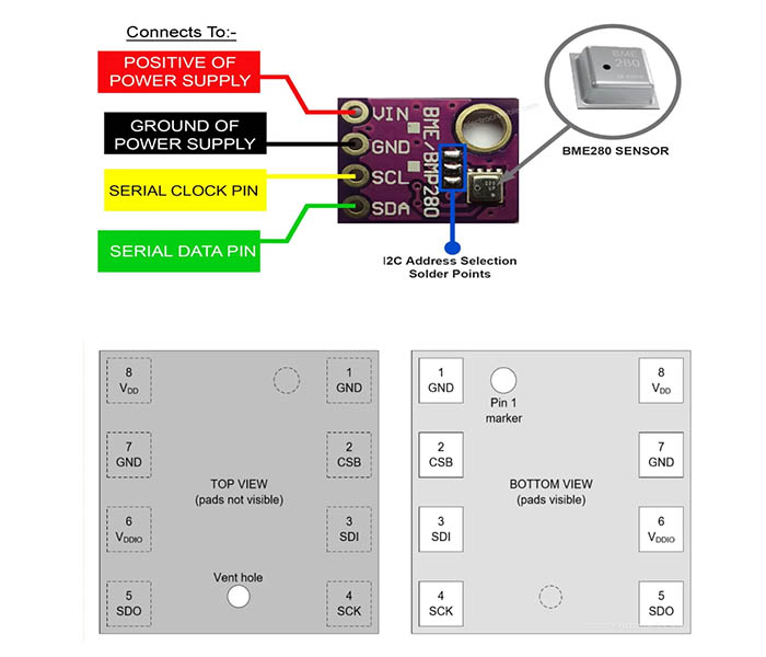
Figure2-BME280 Pinout
- VIN: Connect this to a 1.8V to 5V Power supply positive rail
- GND: Connects to Ground of the Power supply
- SCL: Serial Clock Pin for I2C communication
- SDA: Serial Data Pin for I2C communication
Ⅳ BME280 Pinout Configuration
|
Pin Number |
Pin Name |
Pin Description |
|
1 |
GND |
Ground |
|
2 |
CSB |
Chip Select |
|
3 |
SDI |
Serial Data Interface |
|
4 |
SCK |
Serial Clock Interface |
|
5 |
SDO |
Serial Data Output |
|
6 |
VDDIO |
Digital/Interface Supply |
|
7 |
GND |
Ground |
|
8 |
VDD |
Analog Supply |
Ⅴ Communication Interface
The BME280 pressure and temperature sensor supports three communication interface methods: four-wire SPI, three-wire SPI, and I2C. In different interface modes, the definition of each pin is also different. The purpose of each pin in these three interface modes is as follows:
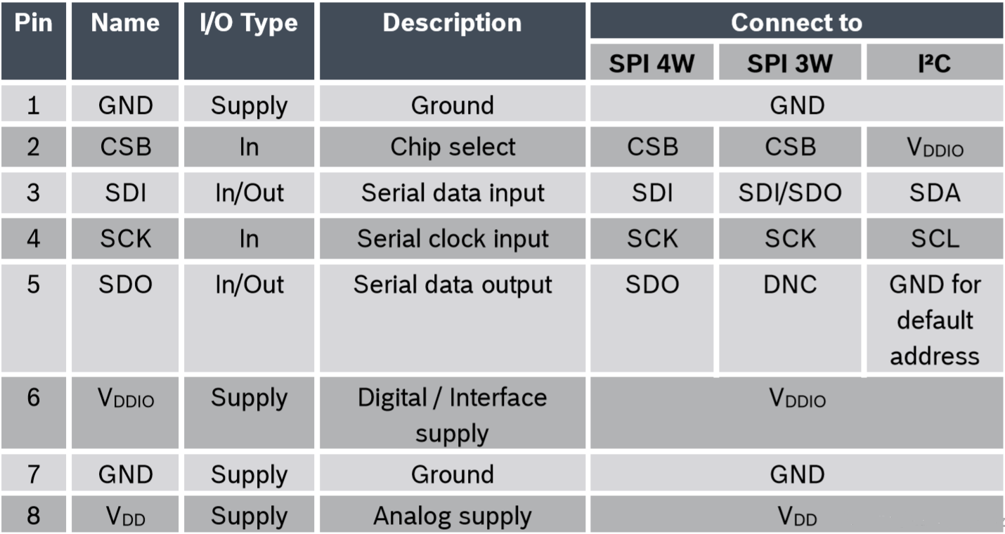
Figure3-Communication Interface
Corresponding to three different interface modes, there are three ways to connect the BME280 pressure temperature sensor to the bus. First, let's look at the four-wire SPI interface mode, including CSB chip selects, SCK clock, SDI digital input, and SDO digital output. The bus connection method is as follows:
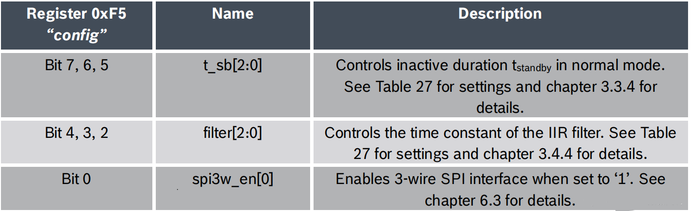
Figure4-four-wire SPI interface
Next, let's discuss the three-wire SPI interface mode, including CSB chip selects, SCK clock, and SDI digital input/SDO digital output. The difference between it and 4-wire SPI is that the digital input and output use the same pin, the third pin is both input and output, and the fifth pin is floating. The bus connection method is as follows:
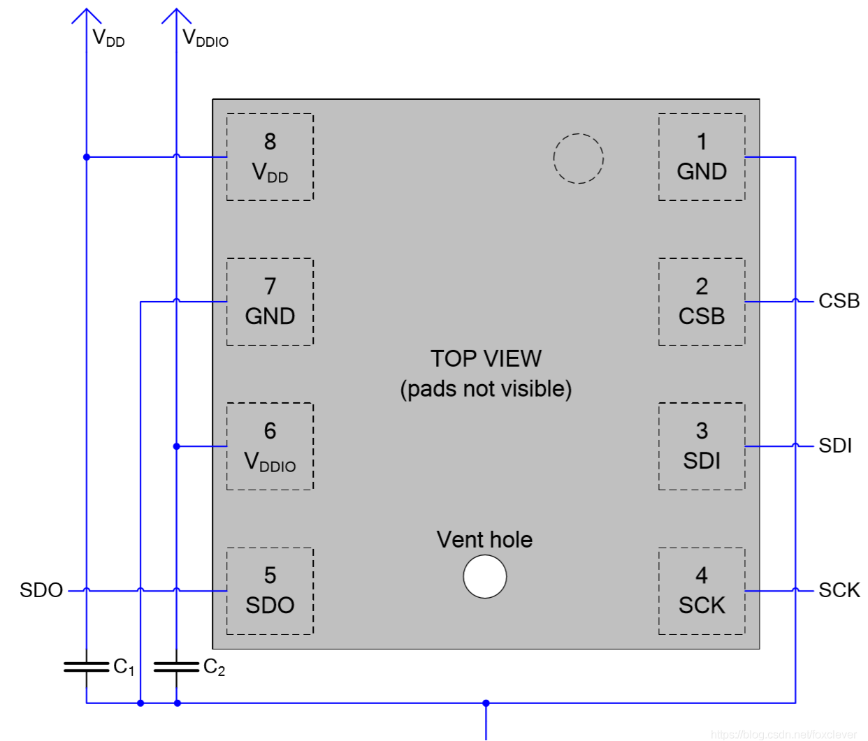
Figure5-four-wire SPI interface
Finally, let's explore the I2C interface mode, including the SCL clock, SDA digital input, and output. In the I2C interface mode, the second pin CSB is connected to a high level to set the BME280 pressure temperature sensor to use the I2C interface. And pin 5 can set the last digit of the device address by connecting high level or low level, and it cannot be left floating. Therefore, according to the different frequencies of pin 5, the 7-bit address of the I2C device of the BMP280 pressure temperature sensor is 0x76 and 0x77. The bus connection method is as follows:

Figure6-four-wire SPI interface
Ⅵ Internal Register
All operations on the BME280 pressure and temperature sensor are realized by reading and writing the corresponding registers. All registers in the BME280 pressure temperature sensor are 8 bits. The address allocation of these registers in memory is shown in the figure below.

Figure7-internal register
The registers reserved by the system are not included in the above figure. These registers cannot be written, and the read values are also meaningless. Next, let's describe these registers in the above figure in detail.
Let's take a look at two special registers first. The first is the ID register, which is read-only, and its stored value is also fixed at 0x60, which is used to represent that the device is a BME280 pressure and temperature sensor. This register can be read after the system is powered on. There is also a reset register, which is write-only, and 0xB6 is fixedly written to it to reset the BME280 pressure and temperature sensor. Also, the reset register can be written after the system is powered on.
The humidity control register is used to configure the measurement accuracy of humidity data. However, modifying the value of this register will not take effect immediately, and it will be effective only after writing to the measurement control register. The definition of each bit of the humidity control register is as follows:
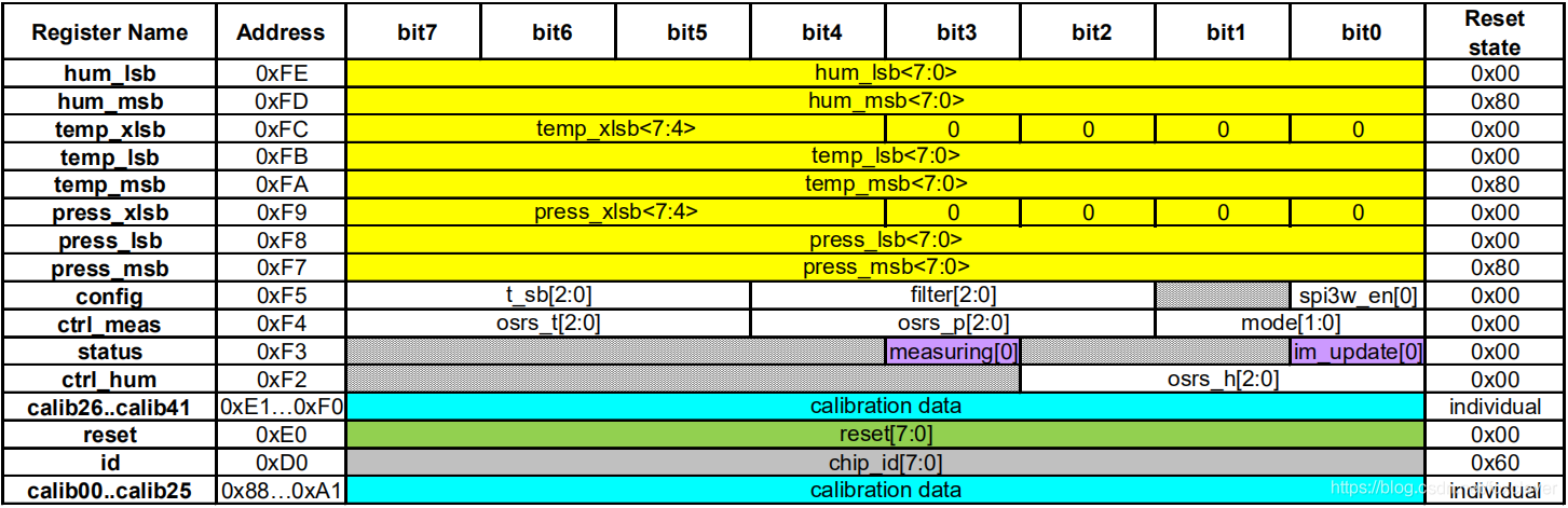
Figure7- ID register
The status register is read-only. Only two bits are used. These two bits respectively indicate whether the data measurement is completed and whether the impact register is updated. The following figure is a detailed description of the status register:
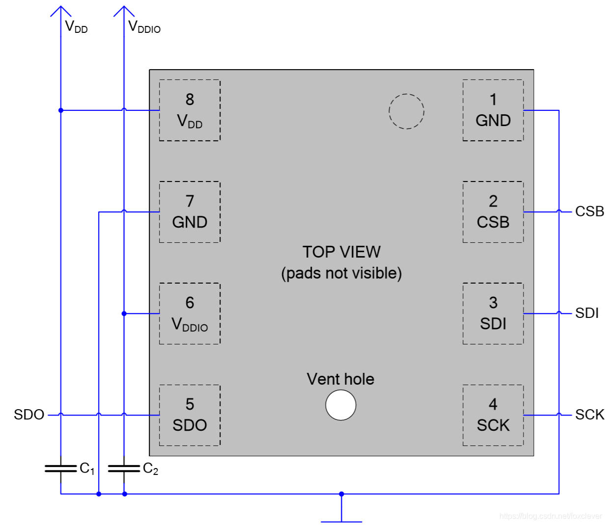
Figure8-status register
The measurement control register is readable and writable and is used to configure the data acquisition method of the BME280 pressure and temperature sensor. Configure temperature sampling, pressure sampling, and working mode respectively. There are three working modes: sleep mode, forced mode, and normal mode. After the system is powered on, it will be in sleep mode. Through the configuration of this register, the BME280 pressure and temperature sensor can enter forced mode or normal mode. After the humidity controller is modified, this register must be written to take effect. The definition of each bit of the measurement control register is as follows:
Ⅶ BME280 Specifications
Let us go into detail about the temperature, humidity, and pressure sensor onboard the BME280 module.
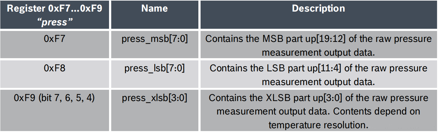
Figure9-BME280 Specifications
The configuration register is used to set the rate, filter, and interface mode of the BME280 pressure temperature humidity sensor. Writing configuration registers is allowed in sleep mode, but will be ignored in normal mode, so after the system reset, write configuration registers before entering normal mode. The definition of each bit of the configuration register is shown in the figure below:

Figure9-pressure data
The pressure data register stores the raw value of the pressure measurement data output. 20 bits of the three registers are used to store pressure data. The definition of each bit of the pressure data register is shown in the figure below:

Figure9-temperature data
The temperature data register stores the raw value of the temperature measurement data output. 20 bits of the three registers are used to store temperature data. The definition of each bit of the temperature data register is shown in the figure below:
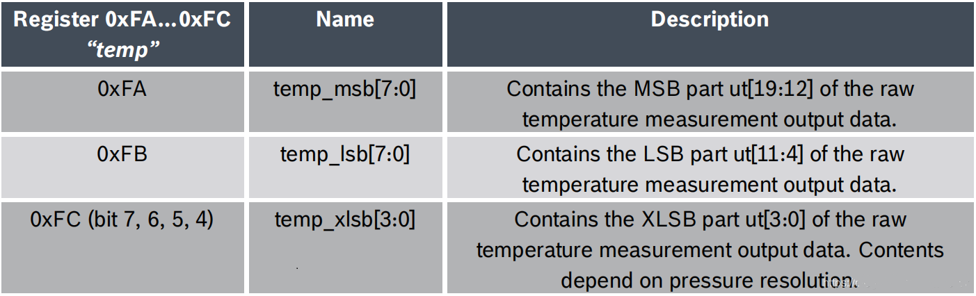
Figure9-humidity data
The humidity data register stores the raw value of the humidity measurement data output. 16 bits of the two registers are used to store the humidity data. The definition of each bit of the humidity data register is shown in the figure below:
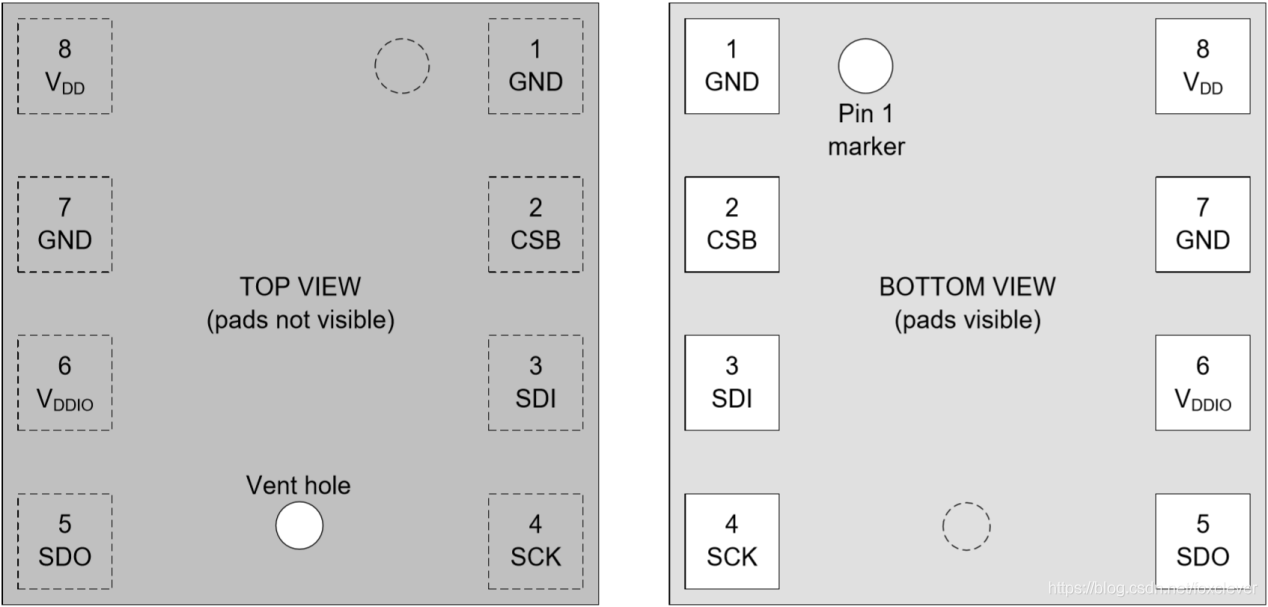
Figure10-humidity data register
In addition, there are calibration data registers, a total of 41 registers, which store the factory calibration data for calculating the final value of pressure and temperature. The definition and address allocation of these calibration registers is shown in the figure below:
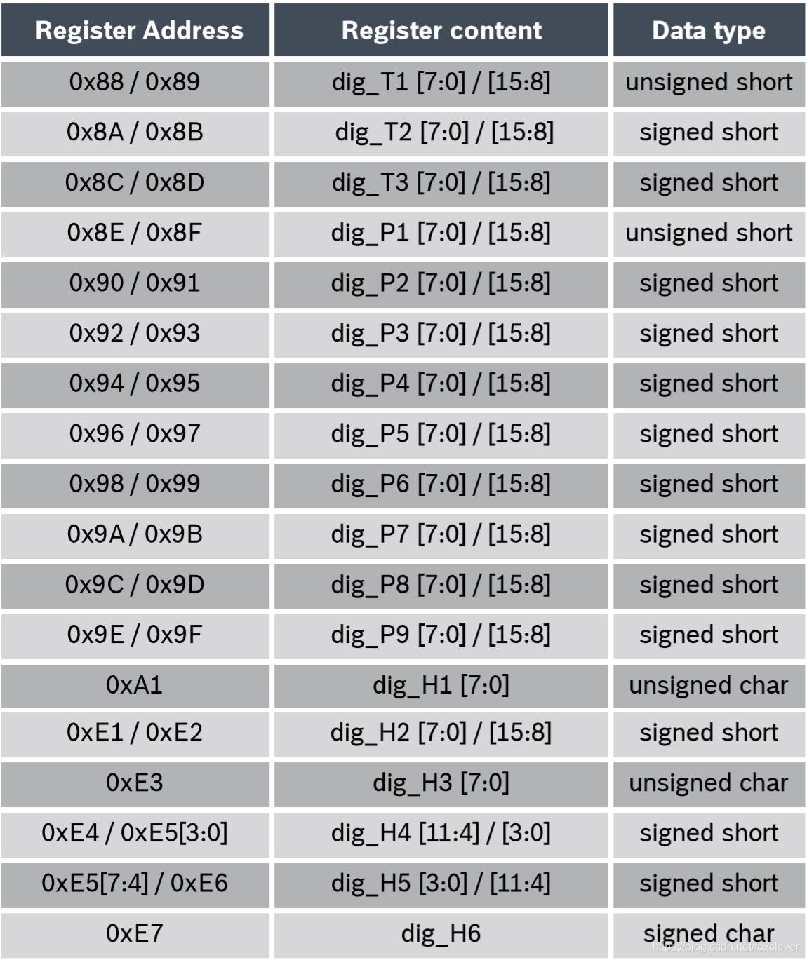
Figure11-calibration data registers
Ⅷ Humidity Sensor Specifications
The humidity sensor inside BME280 is a Relative Humidity (%RH) sensor that is fast and accurate. Here are its specs:
- Response time: 1 sec (at 25°C).
- Accuracy: ±3% (at 25°C).
- Operating temperature range: -40 °C to 85 °C but with a limited measuring range in the extremes. Can detect 0 to 100% Relative Humidity when operating from 0 °C to 60 °C.
- Maximum current consumption by the sensor: 2.8 µA.
- Resolution= 0.008 %RH
Temperature Sensor Specifications
- Accurate measuring range: 0 to 65 °C.
- Current consumption: 1 µA.
- Accuracy: ±1.0 °C from 0 to 65 °C.
- Resolution: 0.01 °C.
Pressure Sensor Specifications
- The operating range for accurate measurements: 0 to 65 °C.
- Operating pressure range: 300 to 1100 hPa.
- Maximum current consumption by the sensor: 4.2 µA.
- HighestResolution:18 Pa.
Note: Accuracy denotes the closeness of a measured value to the true or actual value. Resolution is the smallest change in measurement that can be measured by a sensor.
Ⅸ Block Diagram
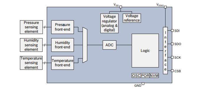
Figure12-Block Diagram of Bme280
Ⅹ How to use the BME280 Sensor IC
Any microcontroller that supports the I2C or SPI communication interface can be simply interfaced with the BME280. Two wires are needed to power the sensor and two wires are needed for I2C communication, totaling four wires for interface. Using the same data lines, multiple sensors can be linked together. The BME280 sensors need to be configured with unique I2C addresses in this situation.
Here is an illustration of a BME280 schematic using a Raspberry Pi Pico.
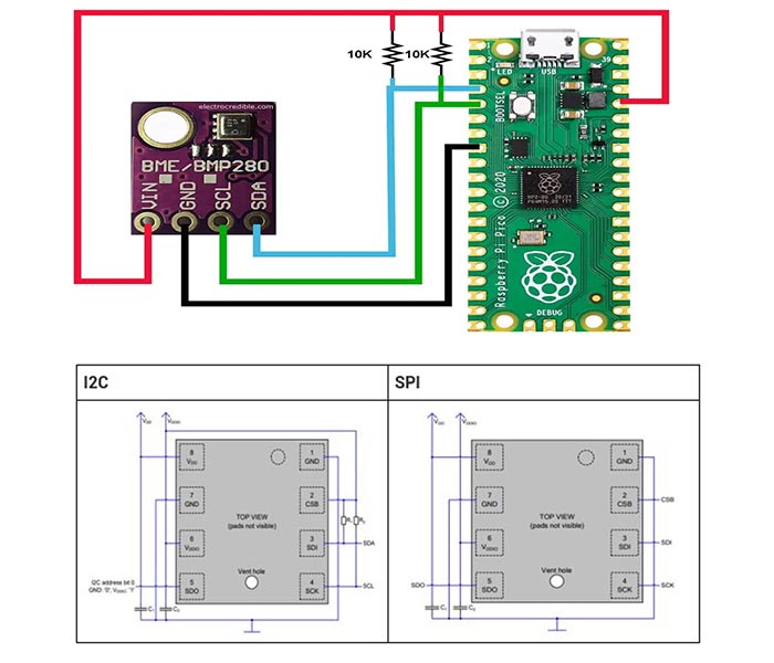
Figure13-How to use the BME280 Sensor IC
Ⅺ Applications
- Context awareness, e.g. skin detection, room change detection
- Fitness monitoring/well-being
- Measurement of volume and airflow
- Home automation control
- control heating, venting, air conditioning (HVAC)
- Internet of things
- GPS enhancement (time-to-first-fix improvement, dead reckoning, slope detection)
- Indoor navigation (change of floor detection, elevator detection)
- Outdoor navigation, leisure, and sports applications
- Weather forecast
- Vertical velocity indicator (rise/sink speed)
Ⅻ Target Devices
- Handsets such as mobile phones, tablet PCs, GPS devices
- Navigation systems
- Gaming, e.g. flying toys
- Camera (DSC, video)
- Home weather stations
- Flying toys
- Watches
XIII 2D Model and Dimensions
If you are designing a PCB or Perf board with this component then the following picture from the BME280 Datasheet will be useful to know its package type and dimensions.
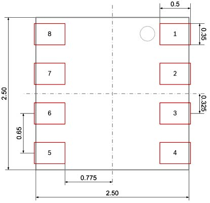
Figure14-2D Model and Dimensions
XIV BME280 PDF
 DC-DC converter RFB-0505S: Specification,Datasheet,Features and Applications6/13/2024 596
The RFB-0505S is a DC-DC converter from RECOM Power, Inc., belonging to the RFB Series. It features a Single In-Line Package (SIP7) and provides a single unregulated output. This converter offers 1 watt of power with an output voltage of 5V and is rated for an isolation voltage of 1kV.
Read More > Understanding the RFMM-0505S DC-DC Converter: A Comprehensive Guide6/4/2024 779
In the world of electronics, ensuring efficient power management is crucial for the performance and reliability of devices. One of the key components in achieving this is the DC-DC converter. Today, we dive into the specifics of the RFMM-0505S DC-DC converter, exploring its features, applications, and benefits.
Read More > 12V DC-DC Converter AM2G-0512SZ: Specifications, Datasheet, Applications and Features6/3/2024 695
A DC-DC converter is an essential electronic device to convert a direct current (DC) source from one voltage level to another. These converters are widely employed in various applications, including portable electronic devices, automotive systems, and renewable energy installations.
Read More > What is LM3900 Quadruple Norton Operational Amplifier?5/30/2024 1383
The LM3900 consists of four independent dual-input internally compensated amplifiers. These amplifiers are specifically designed to operate on a single power supply voltage and provide a large output voltage swing. They utilize current mirrors to achieve in-phase input functionality. Applications include AC amplifiers, RC active filters, low-frequency triangle waves, square wave, and pulse waveform generation circuits, tachometers, and low-speed, high-voltage digital logic gates.
Read More > Exploring the MMBT3906 Transistor: A Comprehensive Guide5/24/2024 993
The goal of the Taiwan Semiconductor MMBT3906 PNP Bipolar Transistor is to provide a high surge current capability with minimal power loss. This transistor is perfect for automated installation and has high efficiency.
Read More >
SUPPORT
ABOUT BITFOIC
QUICK LINKS
Connect with us
Tel: 86-755-23606554
E-mail: [email protected]
Address: Room A29, 24 / F, Hoi Tak Wai, Prince Edward industrial building, 706 Prince Edward Road East, San Po Kong, Kowloon,Hongkong
Mon-Fri: 09.30 AM - 18.30 PM


