


Audio Amplifier IC LM386: Datasheet,Pinout,Circuits,Application and Features
Introduction
LM386 is an audio power amplifier produced by the National Semiconductor Corporation of the United States, which is mainly used in low-voltage consumer products. To minimize external components, the voltage gain is built in at 20. But by adding an external resistor and capacitor between pin 1 and pin 8, the voltage gain can be adjusted to any value up to 200. The input is ground-referenced, while the output is automatically biased to half the supply voltage. Its quiescent power consumption is only 24mW at 6V supply voltage, making the LM386 especially suitable for battery-powered applications.
How to make an LM386 audio amplifier circuit
Catalog
Ⅰ What is Audio Amplifier IC LM386?
The LM386 IC is available in an 8-pin dual in-line package (DIP-8). The voltage gain of the amplifier can be adjusted up to 20, which can be increased to 200 by adding external components like resistors and capacitors between pins 1 and 8.
The LM386 IC amplifier consists of 8 pins, of which pin 1 and pin 8 are gain control pins that allow volume control. Depending on the model, the amplifier can deliver output power in the range of 0.25W to 1W from a 9 V supply.
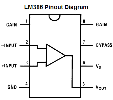
Figure1-LM386 pinout
Ⅱ LM386 Pinout and Configurations
Pin1 (Gain): The gain pin is used to adjust the amplifier gain by connecting the IC to an external component capacitor.
- Pin 2 (Input -): Non-inverting input terminal, used to provide an audio signal.
- Pin 3 (Input +): Inverting input terminal, used to provide an audio signal.
- Pin 4 (GND): Ground pin, connected to the ground terminal of the system
- Pin 5 (Vout): The output pin used to provide amplified output audio, connected to the speaker.
- Pin 6 (Vs): Connect to the power supply and accept positive DC voltage.
- Pin 7 (Bypass): Bypass pin for connecting decoupling capacitors.
- Pin 8 (Gain): Gain setting pin, used to control the gain of the amplifier.
From the pin description, we can conclude:
- Pin 1 and Pin 8 represent the gain control terminals of the amplifier. These are the terminals where we can adjust the gain by placing a resistor and capacitor or just a capacitor between these terminals.
- Pin 2 and Pin 3 represent audio input signal terminals. These are the terminals where we put the sound we want to amplify, pin 2 is the negative input, and pin 3 is the positive input.
- Pin 4 is the GND (ground) terminal, which is connected to the ground in the circuit.
- Pin 5 represents the output of the amplifier. The amplified signal is output from this terminal.
- Pin 6 receives a positive DC voltage so that the amplifier can receive the power needed to amplify the signal.
- Pin 7 represents the bypass terminal. This terminal can be bypassed with a 15KΩ resistor. In circuit design, it is usually left open or grounded.
However, for better stability, a capacitor can be added to the circuit to prevent oscillations in the op-amp IC.
|
Pin Number |
Pin Name |
Description |
|
1,8 |
GAIN |
Used to set the gain of the IC by connecting to a Capacitor |
|
2 |
Inverting Input (IN-) |
The Inverting Pin of the amplifier is normally grounded |
|
3 |
Non-Inverting Input (IN+) |
The Non-Inverting pin is provided with the audio signal |
|
4 |
Ground |
The ground pin is connected to the ground of the system |
|
5 |
Vout |
Provides amplified audio output, connected to the speaker |
|
6 |
Vss/Vcc |
Connected to power |
|
7 |
Bypass |
A bypass pin is used for connecting a decoupling capacitor |
Ⅲ LM386 CAD Model
LM386 symbol
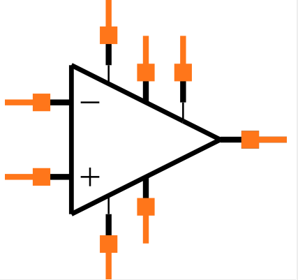
Figure2-LM386 symbol
LM386 footprint
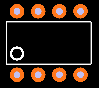
Figure3-LM386 footprint
LM386 3D model
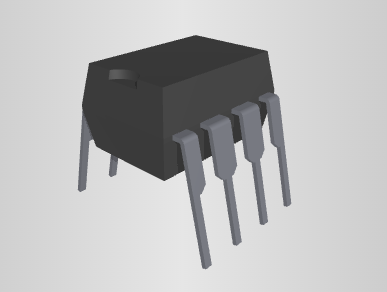
Figure4-LM386 3D model
Ⅳ LM386 Parameters
- Low noise and low distortion circuit
- Small size (8-pin immersion package)
Only 24mW Quiescent Power from 6V Supply
- Standby current consumption is only 4mA
- Operates from a wide supply voltage of 4V to 18V
- Minimum to the maximum voltage gain of 20 to 200
- Also manufactured in VSSOP and SOIC packages.
Sufficient power is available—approximately 700mW of common power output at VS = 9V, RL = 8Ω, THD = 10%.
- Consumes low supply current – 4mA to 8mA with no input signal.
- By connecting a 10uF capacitor between pin 1(+) and pin 8(-), the voltage gain can be increased to 200 or 46dB.
Gains between 20 and 200 can be easily controlled by placing a resistor in series with a capacitor.
- Typical low harmonic distortion: 0.2%
- Frequency response is from 40Hz to 100kHz rate.
- Bandwidth: 300kHz in total
|
Audio input type |
Analog Input |
|
Architecture |
Class-AB |
|
Speaker channels (max) |
Mono |
|
Rating |
Catalog |
|
Power stage supply (max) (V) |
18 |
|
Power stage supply (min) (V) |
4 |
|
Load (min) (Ω) |
4 |
|
Output power (W) |
0.325 |
|
THD + N at 1 kHz (%) |
0.2 |
|
Iq (typ) (mA) |
4 |
|
Control interface |
Hardware |
|
Closed/open loop |
Closed |
|
Analog supply (min) (V) |
4 |
|
Analog supply voltage (max) (V) |
18 |
|
PSRR (dB) |
50 |
|
Operating temperature range (°C) |
0 to 70 |
Ⅴ LM386 working principle
LM386 circuits
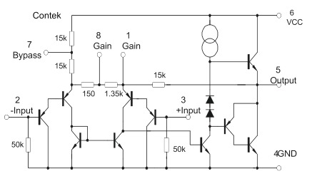
Figure5-LM386 circuits
How to use LM386?
The LM386 only needs a few capacitors and resistors to start working. A very basic common LM386 circuit is shown below:
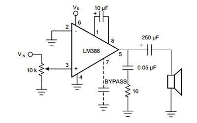
Figure6-How to use LM386
The IC uses pin 6 (usually 5 or 9V) for power and ground pin 4 for ground. The inverting pin (pin 2) is usually ground and the non-inverting pin (pin 3) provides the audio signal.
This audio signal can come from a microphone or even a 3.5 mm jack. A 10k resistor is added in series with the audio signal and acts as a volume control. You can ignore this potentiometer if you want the full-volume operation.
Pin 1 and Pin 8 are used to set the gain of the amplifier. If nothing is connected between these pins, the default gain will be 26 dB, but we can connect a 10 uF capacitor across it to get the maximum gain of the IC which is 46 dB. Pin 7 is used to connect the filter capacitor (0.1uf) of our amplifier IC to avoid unwanted oscillations.
The amplified audio signal can be obtained from pin 5 through a filter capacitor connected to an 8-ohm speaker. RC network with 0.05uF and 10k resistors is optional.
Ⅵ LM386 Audio Amplifier Circuit Diagram
The audio amplifier can be built using LM386 IC, 100 µF, 1000 µF, 0.05 µF, 10 µF, etc capacitors, 10 KΩ potentiometer, 10 KΩ resistor, 12V power supply, 4Ω speaker, breadboard and hookup wires.
Basically, this audio amplifier consists of 3 functional blocks power supply as well as output, bypass, and gain control. The design of this circuit design is very simple. First, connect the two power supply pins, pin4, and pin6, to GND and the corresponding voltage.
After that, connect the input from any type of audio source like your phone or microphone. Here the circuit uses a mobile phone as an audio source via a 3.5mm connector. This connector will have three connections such as ground left and right audio.
This LM386 IC is a simple amplifier to which either the right or left audio is connected using an audio source with a ground terminal. The input level in this circuit can be controlled by connecting a potentiometer to the input. Additionally, a capacitor will be placed in series with the input to remove the DC component. The gain of this IC will be adjusted to 20 and a capacitor (10 µF) is connected between the two pins 1 and 8 of this IC, then the gain will be boosted to 200.
Although the audio amplifier's datasheet suggests that connecting a bypass capacitor at pin 7 is an option, we think connecting a capacitor (100 µF) is really helpful as it helps reduce noise.
For the connection of the output, a capacitor (0.05 µF) and a resistor (10 Ω) will be connected in series between GND and pin 5 of the IC. This forms a Zobel network and a filter consisting of capacitors and resistors will be used to adjust the input impedance.
Speaker connections can be done with an impedance range of 4 Ω to 32 Ω as the IC can drive any type of speaker within this range. The audio amplifier circuit uses a speaker (4 Ω). It is useful to be able to connect this speaker with a capacitor (1000 µF) as it removes unwanted DC signals.
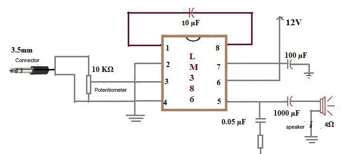
Figure7-LM386 audio amplifier circuit diagram
Ⅶ LM386 power amplifier circuit
LM386 power amplifier circuit --x20 amplifier
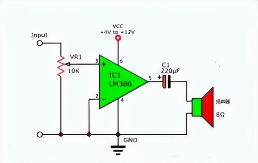
Figure8-LM386 power amplifier circuit --x20 amplifier
The smallest amp offers a gain of 20 with the fewest parts. It is indeed an amplifier circuit, albeit with only one IC and one capacitor.
But its output current is very low (low driving power). Therefore, in actual use, we may need a louder sound. We can increase it in a simple way as follows.
LM386 power amplifier circuit--X200 size power amplifier
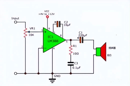
Figure9-LM386 power amplifier circuit--X200 size power amplifier
The gain of this circuit is raised to 200. Because we are connecting the C2 capacitor to the IC through the positive side of C2 at pin 1 and the other positive side at pin 8. But sometimes too high a gain is not good for us, it can be controlled with a resistor.
LM386 power amplifier circuit--X50 low gain
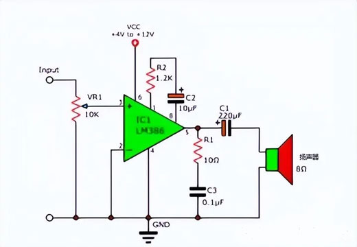
Figure10-LM386 power amplifier circuit--X50 low gain
We added the R2 resistor in series with C2 to reduce the gain to 50.
LM386 power amplifier circuit with bass enhancement function
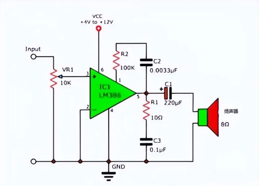
Figure11-LM386 power amplifier circuit with bass enhancement function
Sometimes you may need more bass than usual. The above circuit can be quickly completed. Add the R2 resistor and C2 capacitor in series as above circuit.
This circuit has a bass booster, the output gain depends on the bass frequency. For example, gain 25dB: 100Hz, gain 19dB: 2kHz.
- Adjust volume via VR1.
- Both R1 and C3 will maintain good sound.
- Improved stability for high-frequency loads.
1、 LM386 power amplifier circuit -- 9V
The circuit below is also a 9V amplifier circuit but with a gain of up to 200.
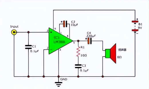
Figure12-LM386 power amplifier circuit -- 9V
1、Parts list
1) 0.25W resistor, tolerance: 5%
R1: 10Ω
- R2: 1.2K
VR1: 10K potentiometer
2) capacitance
- C1: 0.01μF 50V ceramic
- C2: 10μF 25V electrolytic
- C3: 0.1μF 50V ceramic
- C5: 220μF 16V electrolytic
3) Component parts and other devices
- IC1:LM386, Low voltage audio amplifier
- SP1:8Ω 0.25W ·Speaker
- B1:battery,9V
2、Work principle
First, the signal goes to input pin 3, the non-inverting input. This is a signal amplifier in the form of a single phase.
- C1 absorbs noise to protect the input.
- C2 increases the gain of the amplifier.
More gain can be obtained by adding the C2 capacitor. However, higher values result in larger distortion (should be below 100µF).
- Output from pin 5 of IC1.
- The signal goes through the C4 coupling capacitor, which makes the quality of the audio signal better and blocks all DC voltage going to the speaker.
- R1 and C3 are both connected in series, they can better maintain the high-frequency response.
Ⅷ LM386 Application Circuit
1. LM386 square wave oscillator
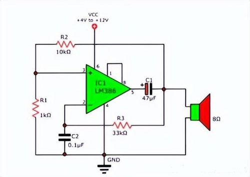
Figure13-LM386 square wave oscillator
The LM386 can also be used to create a square wave oscillator circuit, which makes it easier to create an audible alarm using a speaker. Because this IC is an operational amplifier. Therefore, it is also a good choice when making oscillator circuits.
According to the above circuit, the output frequency is about 1KHz, which can be changed by C2. The larger the capacitance, the lower the frequency, and vice versa.
Ⅸ Applications
The audio amplifier LM 386 IC can be used in various applications. It is one of the most essential chips in the audio section and is often used in the following applications.
- Battery-powered systems such as TV sound systems, ultrasonic drivers, recording sound from microphones
- AM and FM radio amplifiers
- Low Power Audio Amplifiers
- Portable music player
- Laptop/computer speakers and small portable speakers
- Audio Enhancer
- Wien Bridge Oscillator
- Intercom
- Power converter
 DC-DC converter RFB-0505S: Specification,Datasheet,Features and Applications6/13/2024 544
The RFB-0505S is a DC-DC converter from RECOM Power, Inc., belonging to the RFB Series. It features a Single In-Line Package (SIP7) and provides a single unregulated output. This converter offers 1 watt of power with an output voltage of 5V and is rated for an isolation voltage of 1kV.
Read More > Understanding the RFMM-0505S DC-DC Converter: A Comprehensive Guide6/4/2024 710
In the world of electronics, ensuring efficient power management is crucial for the performance and reliability of devices. One of the key components in achieving this is the DC-DC converter. Today, we dive into the specifics of the RFMM-0505S DC-DC converter, exploring its features, applications, and benefits.
Read More > 12V DC-DC Converter AM2G-0512SZ: Specifications, Datasheet, Applications and Features6/3/2024 639
A DC-DC converter is an essential electronic device to convert a direct current (DC) source from one voltage level to another. These converters are widely employed in various applications, including portable electronic devices, automotive systems, and renewable energy installations.
Read More > What is LM3900 Quadruple Norton Operational Amplifier?5/30/2024 1287
The LM3900 consists of four independent dual-input internally compensated amplifiers. These amplifiers are specifically designed to operate on a single power supply voltage and provide a large output voltage swing. They utilize current mirrors to achieve in-phase input functionality. Applications include AC amplifiers, RC active filters, low-frequency triangle waves, square wave, and pulse waveform generation circuits, tachometers, and low-speed, high-voltage digital logic gates.
Read More > Exploring the MMBT3906 Transistor: A Comprehensive Guide5/24/2024 914
The goal of the Taiwan Semiconductor MMBT3906 PNP Bipolar Transistor is to provide a high surge current capability with minimal power loss. This transistor is perfect for automated installation and has high efficiency.
Read More >
SUPPORT
ABOUT BITFOIC
QUICK LINKS
Connect with us
Tel: 86-755-23606554
E-mail: [email protected]
Address: Room A29, 24 / F, Hoi Tak Wai, Prince Edward industrial building, 706 Prince Edward Road East, San Po Kong, Kowloon,Hongkong
Mon-Fri: 09.30 AM - 18.30 PM


