


ATtiny13 8-bit AVR Microcontroller: Pinout, Features and Datasheet[Video&FAQ]
The high-performance, low-power Microchip 8-bit AVR® RISC-based microcontroller combines 1 KB ISP Flash memory, 64B SRAM, 64B EEPROM, a 32B register file, and a 4-channel 10-bit A/D converter. The device supports a throughput of 20 MIPS at 20 MHz and operates between 2.7-5.5 volts. By executing powerful instructions in a single clock cycle, the device achieves throughputs approaching one MIPS per MHz, balancing power consumption and processing speed.
How to program ATtiny13A with Arduino
Catalog
ⅠATtiny13 Overview
The ATtiny13 is a low-power CMOS 8-bit microcontroller based on the AVR-enhanced RISC architecture. By executing powerful instructions in a single clock cycle, the ATtiny13 achieves throughputs approaching 1 MIPS per MHz allowing the system designer to optimize power consumption versus processing speed.
ⅡATtiny13 CAD Model
Symbol
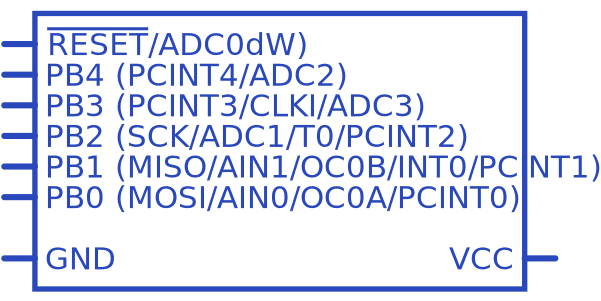
Figure1-Symbol
Footprint

Figure2-Footprint
ⅢATtiny13 Pinout
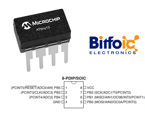
Figure3-ATtiny13 Pinout
ⅣATtiny13 Pin Configuration
|
Pin Number |
Pin Name |
Description |
|
1 |
(PCINT5/RESET/ADC0/dW)PB5 |
Pin of Port B Bit 5 or ADC Input Channel 0 or debugWIRE I/O or Pin Change Interrupt 0, source 3 or Reset pin mainly used for programming |
|
2 |
(PCINT3/CLKI/ADC3) PB3 |
Bidirectional I/O Pin of Port B Bit 3 or ADC Input Channel 3 or External Clock Input or Pin Change Interrupt 0, source 3 |
|
3 |
(PCINT4/ADC2) PB4 |
Bidirectional I/O Pin of Port B Bit 4 or ADC Input Channel 2 or Pin Change Interrupt 0, source 4 |
|
4 |
GND |
Ground Pin of MCU |
|
5 |
PB0 (MOȘI/AIN0/OC0A/PCINT0) |
Bidirectional I/O Pin of Port B Bit 0 or SPI MOSI used for programming or Analog comparator + or Pin change interrupt0, source 0 or Timer/Counter0 compare Match A Out |
|
6 |
PB1 (MISO/AIN1/OC0B/INT0/PCINT1) |
Bidirectional I/O Pin of Port B Bit 1 or Analog comparator input - or External input 0 input or Timer/Counter1 Compare Match B Out or Pin Change Interrupt 0, source 1 or SPI MISO used for programming |
|
7 |
PB2 (SCK/ADC1/T0/PCINT2) |
Bidirectional I/O Pin of Port B Bit 2 or ADC Input Channel 1 or Timer/Counter0 Clock Source or Serial Clock input or Pin Change Interrupt 0, source 2 or external clock input, used for programming |
|
8 |
VCC |
Positive Pin of MCU (+5V) |
ⅤATtiny13 Features
- High Performance, Low Power AVR® 8-Bit Microcontroller
- Advanced RISC Architecture
– 120 Powerful Instructions
– Most Single Clock Cycle Execution
– 32 x 8 General Purpose Working Registers
– Fully Static Operation – Up to 20 MIPS Throughput at 20 MHz
- High Endurance Non-volatile Memory Segments
– 1K Bytes of In-System Self-programmable Flash program memory
– 64 Bytes EEPROM – 64 Bytes Internal SRAM
– Write/Erase cyles: 10,000 Flash/100,000 EEPROM
– Data retention: 20 years at 85°C/100 years at 25°C
– Programming Lock for Self-Programming Flash & EEPROM Data Security
- Peripheral Features
– One 8-bit Timer/Counter with Prescaler and Two PWM Channels
– 4-channel, 10-bit ADC with Internal Voltage Reference
– Programmable Watchdog Timer with Separate On-chip Oscillator
– On-chip Analog Comparator
- Special Microcontroller Features
– debugWIRE On-chip Debug System
– In-System Programmable via SPI Port
– External and Internal Interrupt Sources
– Low Power Idle, ADC Noise Reduction, and Power-down Modes
– Enhanced Power-on Reset Circuit
– Programmable Brown-out Detection Circuit
– Internal Calibrated Oscillator
- I/O and Packages
– 8-pin PDIP/SOIC: Six Programmable I/O Lines
– 20-pad MLF: Six Programmable I/O Lines
- Operating Voltage:
– 1.8 - 5.5V for ATtiny13V
– 2.7 - 5.5V for ATtiny13
- Speed Grade
– ATtiny13V: 0 - 4 MHz @ 1.8 - 5.5V, 0 - 10 MHz @ 2.7 - 5.5V
– ATtiny13: 0 - 10 MHz @ 2.7 - 5.5V, 0 - 20 MHz @ 4.5 - 5.5V
- Industrial Temperature Range
- Low Power Consumption
– Active Mode:
- 1 MHz, 1.8V: 240 µA
– Power-down Mode:
- < 0.1 µA at 1.8V
Note: Complete technical details can be found in the ATtiny13 Datasheet, linked at the bottom of this page.
ⅥATtiny13 Block Diagram
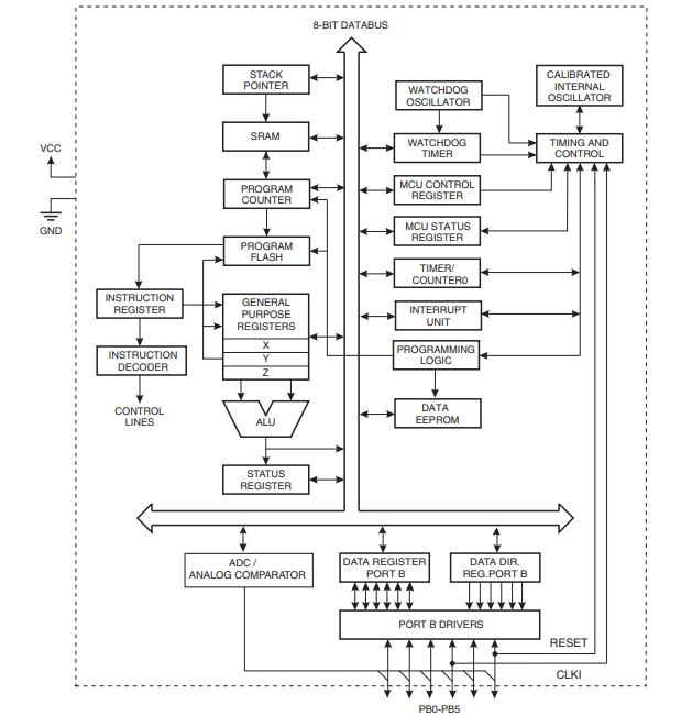
Figure4-ATtiny13 block diagram
ⅦATtiny13 Alternative Parts
ATtiny2313A (Exact Alternative with the new release)
ATtiny417, ATtiny28L, ATtiny48, ATmega88PA, ATmega8A, ATmega8515, ATmega8535, ATmega645A, ATmega645A, ATmega6490
ⅧATtiny13 Package
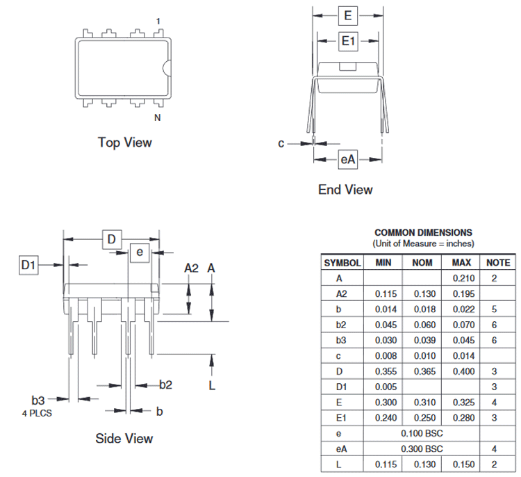
Figure5-ATtiny13 Package
ⅨATTINY13 vs ATTINY13A
|
|
ATTINY13 |
ATTINY13A |
|
Max ADC Resolution (bits) |
10 |
10 |
|
Program Memory Size (KB) |
1 |
1 |
|
Number of Comparators |
1 |
1 |
|
CPU Speed (MIPS/DMIPS) |
20 |
20 |
|
Data EEPROM (bytes) |
64 |
64 |
|
Max 8-Bit Digital Timers |
1 |
1 |
|
Ethernet |
None |
None |
|
Program Memory Type |
Flash |
Flash |
|
ADC Channels |
4 |
4 |
|
Low Power |
No |
Yes |
|
Operation Voltage Max.(V) |
5.5 |
5.5 |
|
Operation Voltage Min.(V) |
1.8 |
1.8 |
|
output comparator PWM |
2 |
2 |
|
Pin Count |
8 |
8 |
|
Temp. Range Max. |
85 |
125 |
|
Temp. Range Min. |
-40 |
-40 |
|
Summary |
The high-performance, low-power Microchip 8-bit AVR® RISC-based microcontroller combines 1 KB ISP Flash memory, 64B SRAM, 64B EEPROM, a 32B register file, and a 4-channel 10-bit A/D converter. The device supports a throughput of 20 MIPS at 20 MHz and operates between 2.7-5.5 volts. By executing powerful instructions in a single clock cycle, the device achieves throughputs approaching one MIPS per MHz, balancing power consumption and processing speed. |
The Microchip picoPower® 8-bit AVR® RISC-based microcontroller features 1 KB of ISP Flash, 64B EEPROM, 64B SRAM, 32B register file, and 4-channel 10-bit A/D converter. The device achieves up to 20 MIPS throughput at 20 MHz at 1.8-5.5V operation. By executing powerful instructions in a single clock cycle, the ATtiny13A achieves throughputs approaching one MIPS per MHz allowing you to optimize power consumption versus processing speed. |
ⅩATtiny13 Datasheet
ATtiny13 microcontroller PDF
ⅪATtiny13A Manufacturer
Microchip Technology Incorporated is a leading provider of smart, connected, and secure embedded control solutions. Customers may construct the best designs possible with the help of its user-friendly development tools and wide range of products, which minimize total system cost and time to market while reducing risk. More than 120,000 customers use the company's solutions in the industrial, automotive, consumer, aerospace and defense, communications, and computer sectors. Microchip, with headquarters in Chandler, Arizona, provides excellent technical assistance, consistent delivery, and high-quality products.
 DC-DC converter RFB-0505S: Specification,Datasheet,Features and Applications6/13/2024 591
The RFB-0505S is a DC-DC converter from RECOM Power, Inc., belonging to the RFB Series. It features a Single In-Line Package (SIP7) and provides a single unregulated output. This converter offers 1 watt of power with an output voltage of 5V and is rated for an isolation voltage of 1kV.
Read More > Understanding the RFMM-0505S DC-DC Converter: A Comprehensive Guide6/4/2024 768
In the world of electronics, ensuring efficient power management is crucial for the performance and reliability of devices. One of the key components in achieving this is the DC-DC converter. Today, we dive into the specifics of the RFMM-0505S DC-DC converter, exploring its features, applications, and benefits.
Read More > 12V DC-DC Converter AM2G-0512SZ: Specifications, Datasheet, Applications and Features6/3/2024 684
A DC-DC converter is an essential electronic device to convert a direct current (DC) source from one voltage level to another. These converters are widely employed in various applications, including portable electronic devices, automotive systems, and renewable energy installations.
Read More > What is LM3900 Quadruple Norton Operational Amplifier?5/30/2024 1376
The LM3900 consists of four independent dual-input internally compensated amplifiers. These amplifiers are specifically designed to operate on a single power supply voltage and provide a large output voltage swing. They utilize current mirrors to achieve in-phase input functionality. Applications include AC amplifiers, RC active filters, low-frequency triangle waves, square wave, and pulse waveform generation circuits, tachometers, and low-speed, high-voltage digital logic gates.
Read More > Exploring the MMBT3906 Transistor: A Comprehensive Guide5/24/2024 986
The goal of the Taiwan Semiconductor MMBT3906 PNP Bipolar Transistor is to provide a high surge current capability with minimal power loss. This transistor is perfect for automated installation and has high efficiency.
Read More >
SUPPORT
ABOUT BITFOIC
QUICK LINKS
Connect with us
Tel: 86-755-23606554
E-mail: [email protected]
Address: Room A29, 24 / F, Hoi Tak Wai, Prince Edward industrial building, 706 Prince Edward Road East, San Po Kong, Kowloon,Hongkong
Mon-Fri: 09.30 AM - 18.30 PM


