


PC817 Pinout, Features,Parameters,2D dimension,Application and Examples
PC817 is a widely used optocoupler, this article describes the PC817 optocoupler pinout, datasheet, equivalent, features & other details on how and where to use it in your electronic circuits.
Catalog
Ⅰ What is PC817?
The PC817 consists of an infrared emitting diode (IR LED) and a phototransistor optically coupled to it. An infrared emitting diode and a phototransistor are optically coupled together. Electrical signals are transmitted optically between the input side and the output side without any physical connection between the two parties.
The PC817 optocouplers are small and available in a variety of packages. It can be directly connected to any low-voltage DC device or microcontroller. The input voltage will have the same effect from each side of the optocoupler, it will just transfer the signal to the receiver, which will then have a logic signal as output. Optocouplers are versatile due to their small and compact size and their ability to be used for control operations.
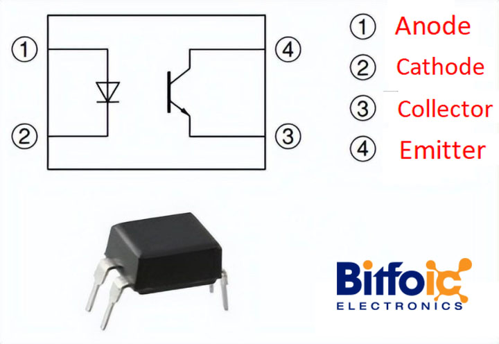
Figure1-PC817
Ⅱ PC817 Pinout
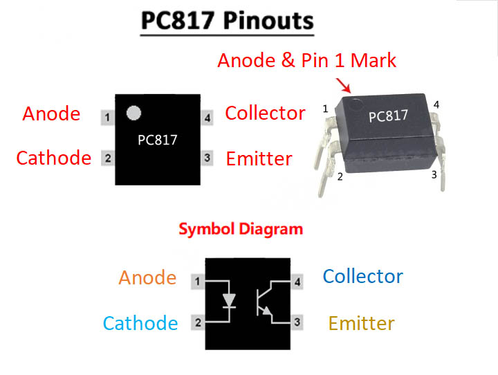
Figure2-PC817 Pinout
IR LED Input:
- Pin 1: Anode (+) pin, inputs logic signal to internal IR.
- Pin 2: Cathode (-) pin, connected to circuit and power supply common ground.
Phototransistor output:
- Pin 3: Emitter pin, establishes a common ground through the circuit and power supply.
- Pin 4: Collector pin, transmits logic output when receiving IR signal.
|
Pin |
Pin name |
Description |
|
1 |
Anode |
Anode pin of the IR LED. Provides logic input to internal IR |
|
2 |
cathode |
The cathode pin of the IRLED, which provides the infrared signal with the circuit and connects the power supply to ground |
|
3 |
Emitter |
The emitter pin of the transistor used to establish common ground through the circuit and the power supply |
|
4 |
collector |
The emitter pin of the transistor acquires the infrared signal and provides a logic output |
Ⅲ How PC817 Works
The working principle of PC817 is very simple, but there are specifications to use it on different devices. The optocoupler at the input needs to be current-limited with a resistor, but at the output, we need to connect the logic output pin with the power supply pin. Whenever an IR signal is generated, the logic state will change from 1 to 0 due to the change in current.
Here is a concrete circuit to show
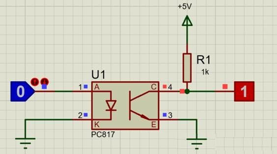
Figure3-PC817 working principle diagram
Here connect the anode pin of the IR LED (pin 1) to a logic input which must be isolated and the cathode of the IR (pin 2) to ground, then use a resistor to pull the collector pin of the transistor high (here I Used 1K) and connected the collector pin to the output of the desired logic circuit and the emitter (pin 4) to ground.
Note: The ground of the IR LED (pin 2) and the ground of the transistor (pin 4) are not connected together. This is where isolation happens.
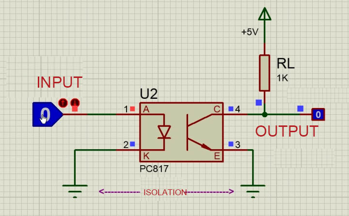
Figure4-PC817 working principle diagram
Now, when the logic input is low, the IR LED will not conduct, so the transistor will also be off so that the logic output will remain high. This high voltage can be set anywhere up to 30V (collector-emitter voltage), I used +5V. There is a pull-up resistor 1K acting as a load resistor.
But when the logic input goes high, this high voltage should be at least 1.25V (diode forward voltage), the IR LED turns on, so the phototransistor also turns on, which will short the collector and emitter, so the logic output voltage will become to zero. This way, the logic input will be reflected on the logic output and still provide isolation between the two.
Another important parameter to consider when using an optocoupler is rise time ( tr ) and fall time (t f ). Once the input logic goes low, the output will not go high and vice versa. The waveform below shows the time it takes for the output to transition from one state to another. For PC817, the rise time (TPD HL ) and fall time (TPD LH ) is 18us.
1. Response Time Test Circuit
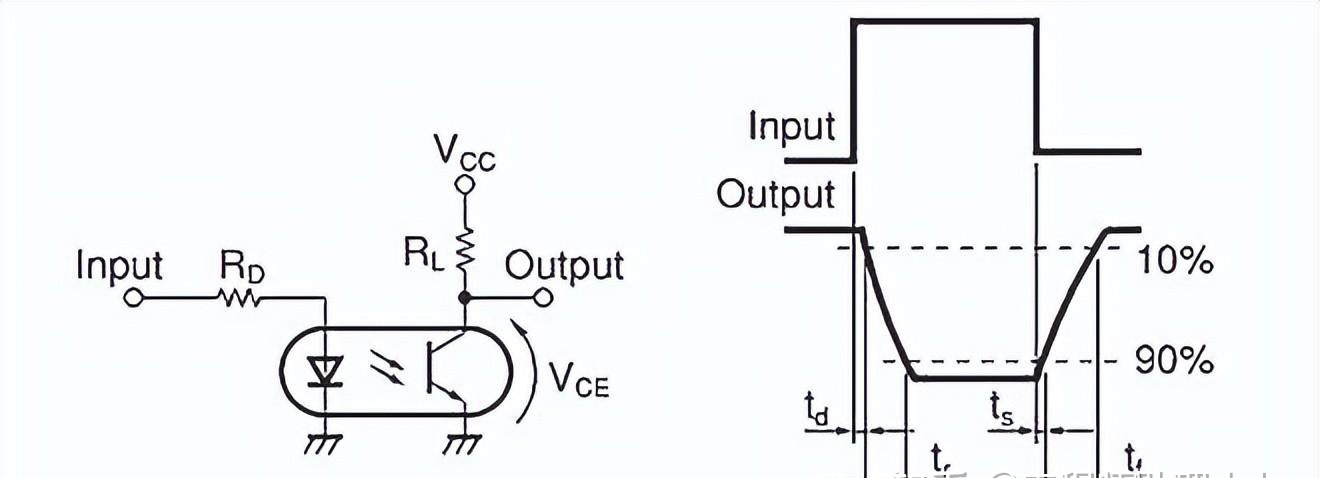
Figure5-Response time test circuit
2. Frequency Response Test Circuit
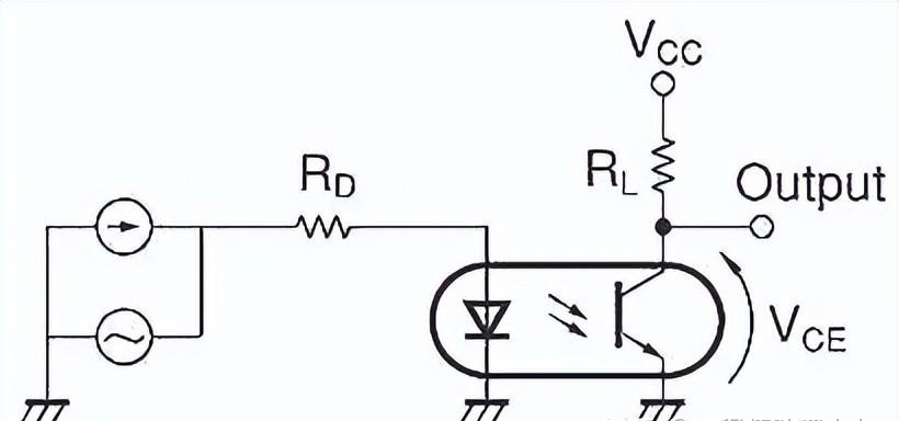
Figure6- Frequency response test circuit
Ⅳ PC817 Optocoupler Parameters
- High VCEO (Collector-Emitter Voltage): 80V MAX
- Input diode forward voltage: 1.25V
- Maximum collector current: 50 mA
80V maximum collector-to-emitter voltage ratio
- 4-pin DIP package and SMT package
- Internal protection of input and output
- CTR (Current Transfer Rate) available for multiple grades
Fall time: 18 μs
Rise time: 18 μs
- Cut-off frequency: 80 kHz
- Maximum power consumption: 200 mW
- High isolation voltage between input and output: 5.0kV
- The maximum operating temperature range is -30 to 100 degrees.
- The internal resistance is 100 Ω.
- The IC's internal storage temperature range is -55 to 125 degrees.
- When soldering, the temperature range of the optocoupler is 260 degrees.
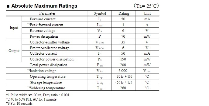
Figure7-PC817 Optocoupler Parameters
Ⅴ Features of PC817 Optocoupler
It is available in 4-pins in both DIP and SMT packages.
The device has an internal form of protection that is electrically isolated. Protection is for input and output. It can protect up to 5KV galvanic isolation.
Optocouplers can be used with external resistors with high-voltage devices to work with low-voltage devices.
Optocouplers can be used with any device that has an internal interface, such as TTL devices, microcontrollers, and even high DC voltages with some internal resistance.
Optocoupler PC817 has internal reverse current protection.
Due to the unidirectional current characteristics of the IR, the PC817 protects the IR from any reverse current.
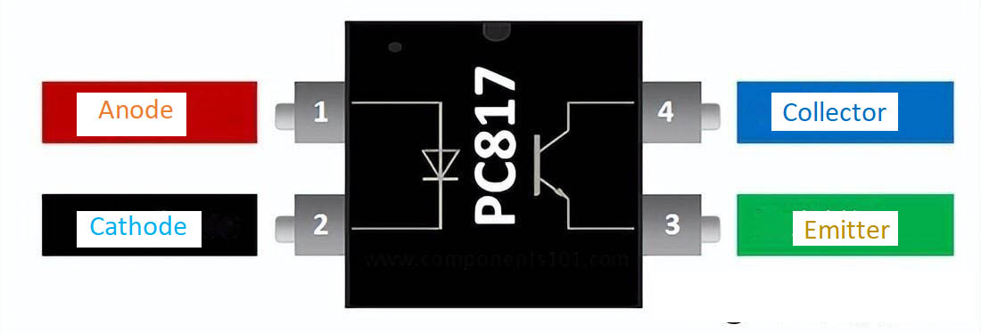
Figure8-Features of PC817 Optocoupler
Ⅵ PC817 equivalent replacement model
- PC817 alternative model:
4N25, 6N136, MOC3021, MOC3041, 6N137
- PC817 equivalent products:
PC817A, PC817C, PC817B, and PC817D
Ⅶ How to judge the quality of the PC817 optocoupler?
- Use a diode to detect
First, take the optocoupler, use a multimeter to measure the input end with the diode file, and replace the red and black test leads. If there is a voltage drop in the forward direction, it will be cut off in the reverse direction, indicating that the front-end LED is normal.
Connect a low voltage 6V to the input terminal (take 4N35 as an example, the specific input voltage is subject to the datasheet), connect a protective resistor in series, adjust the resistance range with a multimeter, and measure the resistance value of the other output terminal.
Disconnect the front-stage power supply with infinite power (generally megohm level), and turn on the front-stage power supply with a sharp drop in resistance value, indicating that the optocoupler is good, otherwise, it is bad.
- Make PC817optocoupler tester circuit
- Use the circuit to detect the PC817 circuit
This circuit primarily intends to perform a functional test of any 4-pin optocoupler IC. For functional testing, place the IC in a female header such that the emitter of the IC's phototransistor and the IR LED anode pin is connected to the circuit's GND, while the IR LED cathode and phototransistor collector pins of the IC are connected to 4V VCC.
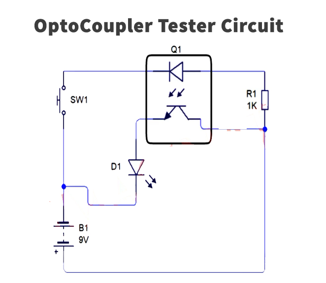
Figure9-PC817 optocoupler test circuit
2) List of electronic components
|
|
Component |
Number of models |
Number |
|
1 |
Optocoupler IC |
PC817 |
1 |
|
2 |
line |
5mm,3.5v |
1 |
|
3 |
button |
|
1 |
|
4 |
resistor |
1k |
1 |
|
5 |
Female |
|
1 |
|
6 |
iron |
45w-65w |
4 |
|
7 |
Flux for welding wire |
|
1 |
|
8 |
panel |
|
1 |
|
9 |
DC battery |
9v |
1 |
|
10 |
battery clip |
|
1 |
|
11 |
Jumper |
|
base on needs |
3) Circuit steps
(1) Solder two pairs of 2 female headers on the panel.
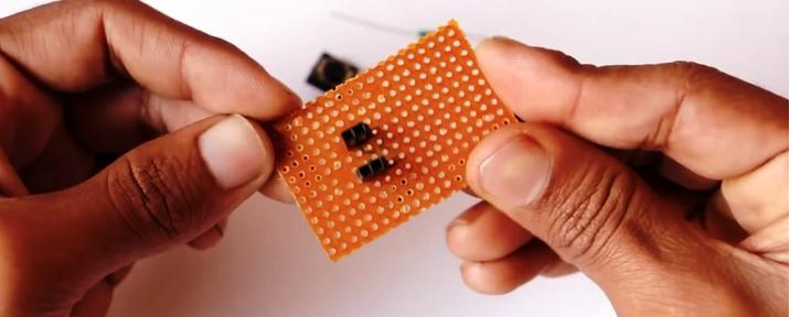
Figure10-PC817 optocoupler good or bad detection
(2) Place a 1K resistor in series between the two female header pairs.
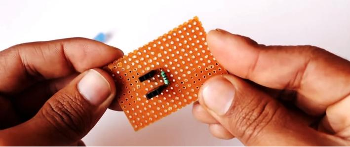
Figure11-PC817 optocoupler good or bad detection
(3) Solder the button and the female head in series
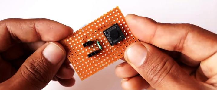
Figure12-Solder the button and the female head in series
(4) Solder the +ve terminal of the LED to the output female and the -ve terminal to the ground of the circuit.
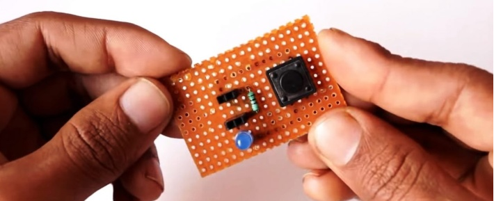
Figure13-Solder the +ve terminal of the LED
(6) Place the optocoupler IC in the female header, power up, and test the circuit.

Figure14-Place the optocoupler IC in the female header
- PC817 optocoupler good or bad detection
- Now, connect the circuit to the power supply, if the LED connected to the emitter lights up when the button is pressed, then the optocoupler IC is working fine. If the LED is off, the IC needs to be replaced.
Ⅷ PC817 optocoupler circuit application
1. PC817 optocoupler circuit
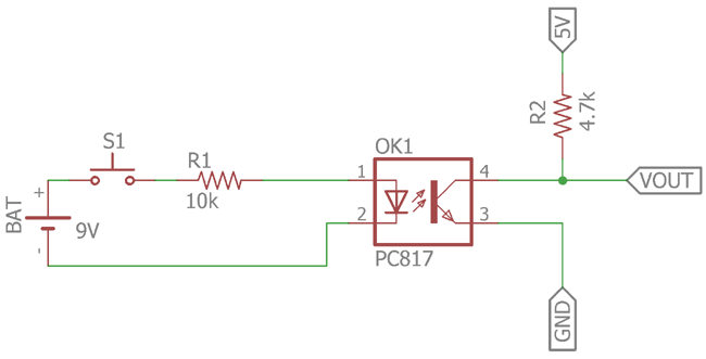
Figure15-PC817 optocoupler circuit
The upper circuit uses an optocoupler circuit based on a phototransistor. It functions like a standard DC transistor switch. A low-cost phototransistor-based optocoupler PC817 is used in the schematic.
The S1 switch will control the IR LED: when the switch is on, the 9V battery supply will supply current to the LED through the 10k current limiting resistor.
The R1 resistor controls the intensity: If we change the value and lower the resistor, the intensity of the LED will be high, resulting in a high gain of the transistor.
On the other side, the triode is a phototransistor controlled by an internal infrared led.
When the LED emits infrared light, the phototransistor makes contact and VOUT goes to zero, turning off the load connected to it. It's important to remember that the collector current of the transistor is 50mA according to the datasheet. VOUT 5v is powered by R2, and the R2 resistor is a pull-up resistor.
Ⅸ 2D Dimension
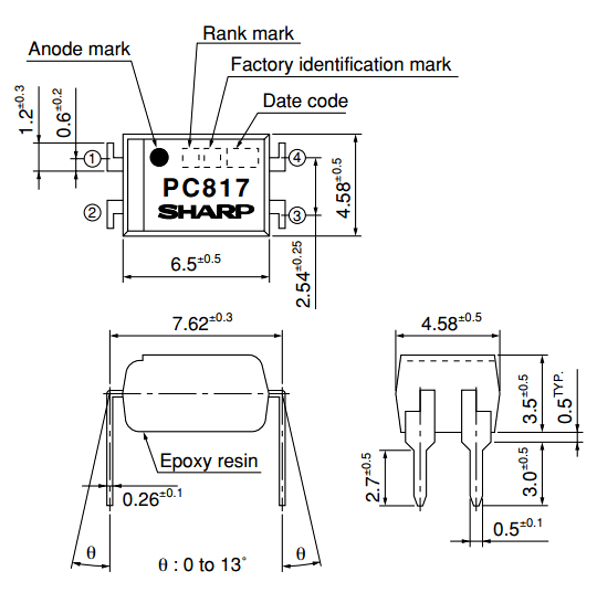
Figure16-2D dimension
Ⅹ PC817 Applications
- In protection like electric isolation, PC 817 is reliable to use due to its functionality.
- PC817 is much more efficient in switching microcontrollers. Simple transistors can be used but due to its neglecting the noise factor the optocoupler can be used as switching too.
- In signal Isolation, the optocoupler was faster and widely used in the previous century.
- Optocoupler is also used for a basic noise coupling circuit to keep the circuit in use without any disconnectivity.
- Nowadays IC has the best uses in IoT devices for switching and zero crosses. An in-home appliance to control AC load optocoupler gives the pulse of change in frequency which gives the ability to control the AC load at a specific range.
- For Signal transmission, the optocoupler is widely used nowadays.
Ⅺ PC817 Examples
The optocoupler has many uses but due to increasing in the IOT field from 2012 the optocoupler is now increasingly used in daily life to control appliances. In IoT especially home automation or heavy load control, we need to control the AC load by the effect of change in frequency. To do so we will need a zero cross. The zero-cross is the method in which we receive the change in the frequency signal of the AC voltages. The change in voltage gives the ability to control the AC. The AC load is further controlled by some TRIACS.
Ⅻ 220V AC Light Dimmer Example with PC817
To use the dimmer we will need to use the microcontroller. Here we will describe a method to control the dimmer with an Arduino.
Interfacing with Arduino
Here’s the circuit:
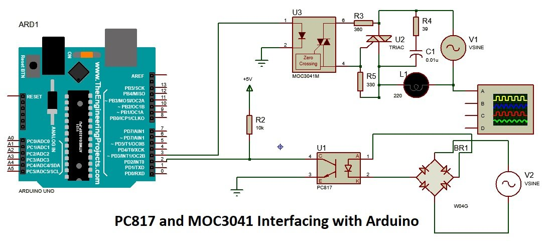
Figure17-220V AC Light Dimmer Example with PC817
The zero cross-pin will be used at the interrupt pin and any digital pins can be used to control the signal. Here’s in the image we describe the pins for IR and dimmer but these pins are not specific. To control the dimmer with the Arduino the following code will be used:
Arduino Sketch
#include <TimerOne.h> volatile int i = 0;
// Variable to use as a counter volatile boolean zero_cross = 0; // Boolean to store a "switch" to tell us if we have crossed zero int AC_pin = 3; // Output to Opto Triac int dim = 128; // Dimming level (0-128) 0 = on, 128 = 0ff int freqStep = 77; // This is the delay-per-brightness step in microseconds. int a = 0; int pin = 13; int data = 0; void setup(){ Serial. begin(9600); pinMode(AC_pin, OUTPUT);// Set the Triac pin as output attachInterrupt(0, zero_cross_detect, RISING); // Attach an Interrupt to Pin 2 (interrupt 0) for Zero Cross Detection Timer1.initialize(freqStep); // Initialize TimerOne library for the freq we need Timer1.attachInterrupt(dim_check2, freqStep); } void zero_cross_detect() { zero_cross = true; // set the boolean to true to tell our dimming function that a zero cross has occurred i = 0; digitalWrite(AC_pin, LOW); } // Turn on the TRIAC at the appropriate time void dim_check2() { if (zero_cross == true) { if (i >= dim) { digitalWrite(AC_pin, HIGH); // turn on light i = 0; // reset time step counter zero_cross = false; // reset zero cross detection } else { i++; // increment time step counter } } } void loop() { if (Serial. available()) { a++; if (a == 1) data = Serial. read(); if (a == 2) { pin = Serial. read(); a = 0; dim = data; } } }
The above code describes how the zero-cross can be used with the Arduino and how the Arduino can control high voltages. The code is just for one dimmer to make it for multiple dimmers the code will require some modifications.
 How to resolve the WiFi and ADC2 Sharing Dilemma?4/19/2024 6
ESP32-CAM can be used in various Internet of Things situations and is suitable for home smart devices, industrial wireless control, wireless Monitoring, QR wireless identification, wireless positioning system signals, and other IoT applications are ideal solutions for IoT applications.
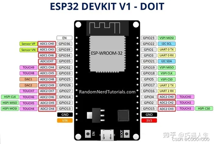
Read More >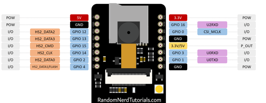 ESP32-CAM Pinout Explanation and How to Use?4/18/2024 13
ESP32-CAM is a development board with an ESP32-S chip, an OV2640 camera, a microSD card slot, and several GPIOs for connecting peripherals. ESP32-CAM is a small-sized camera module. The module can work independently as the smallest system, with a size of only 27*40.5*4.5mm.
Read More >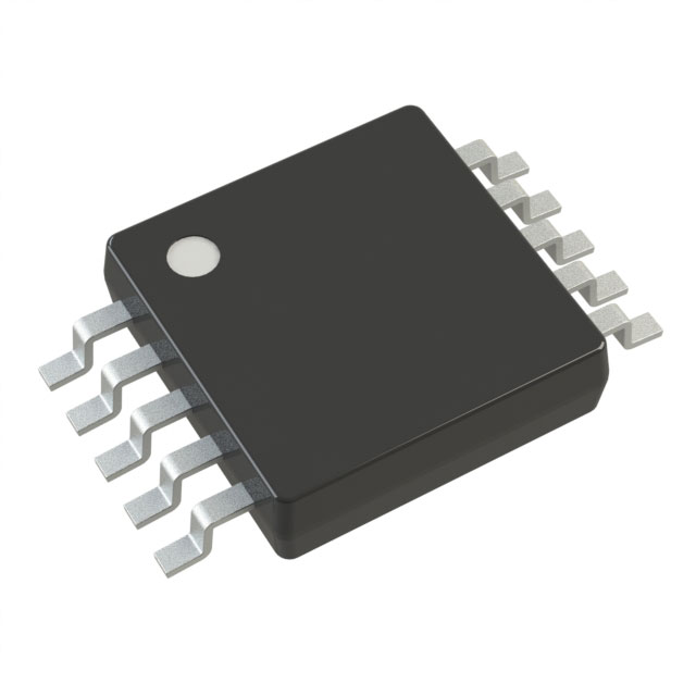 Stand-Alone Linear Li-Ion / Li-Polymer Charge Management Controller MCP738334/9/2024 48
The MCP73833/4 is a highly advanced linear charge management controller for use in space-limited, cost sensitive applications. Both a 10-lead, MSOP and a 10-lead, DFN packaging measuring 3 mm by 3 mm are offered for the MCP73833/4. In addition to its tiny size, the MCP73833/4 is perfect for portable applications because it requires a few additional components.
Read More >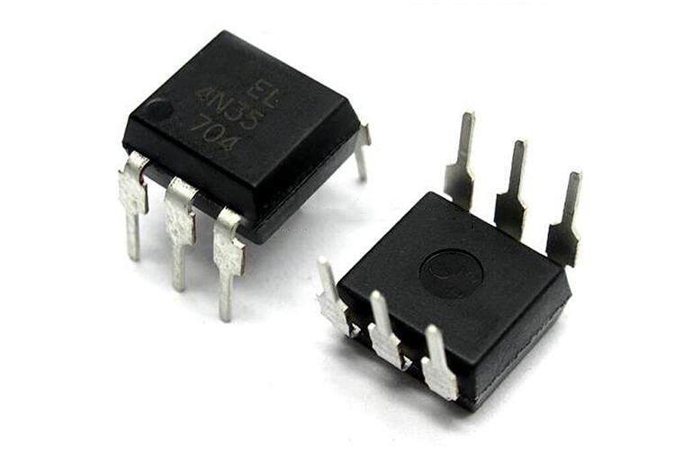 Optocoupler IC 4N35: Pinout, Datasheet, Features and Applications3/26/2024 77
In the realm of electronics, where connectivity and isolation are paramount, the 4N35 optocoupler IC stands as a beacon of reliability and versatility. This small yet mighty device plays a crucial role in ensuring signal integrity and safety across a wide range of applications. In this article, we delve into the intricacies of the 4N35 optocoupler IC, exploring its datasheet, pinout, circuit diagram, and diverse uses.
Read More > UA741CP datasheet ,Specification, Features and Application3/21/2024 80
The UA741CP is a general-purpose operational amplifier in an 8-pin DIP package. The high common-mode input voltage range and lack of latch-up make the amplifier ideal for voltage follower applications.
Read More >
SUPPORT
ABOUT BITFOIC
QUICK LINKS
Connect with us
Tel: 86-755-23606554
E-mail: contact@bitfoic.com
Address: Room A29, 24 / F, Hoi Tak Wai, Prince Edward industrial building, 706 Prince Edward Road East, San Po Kong, Kowloon,Hongkong
Mon-Fri: 09.30 AM - 18.30 PM


